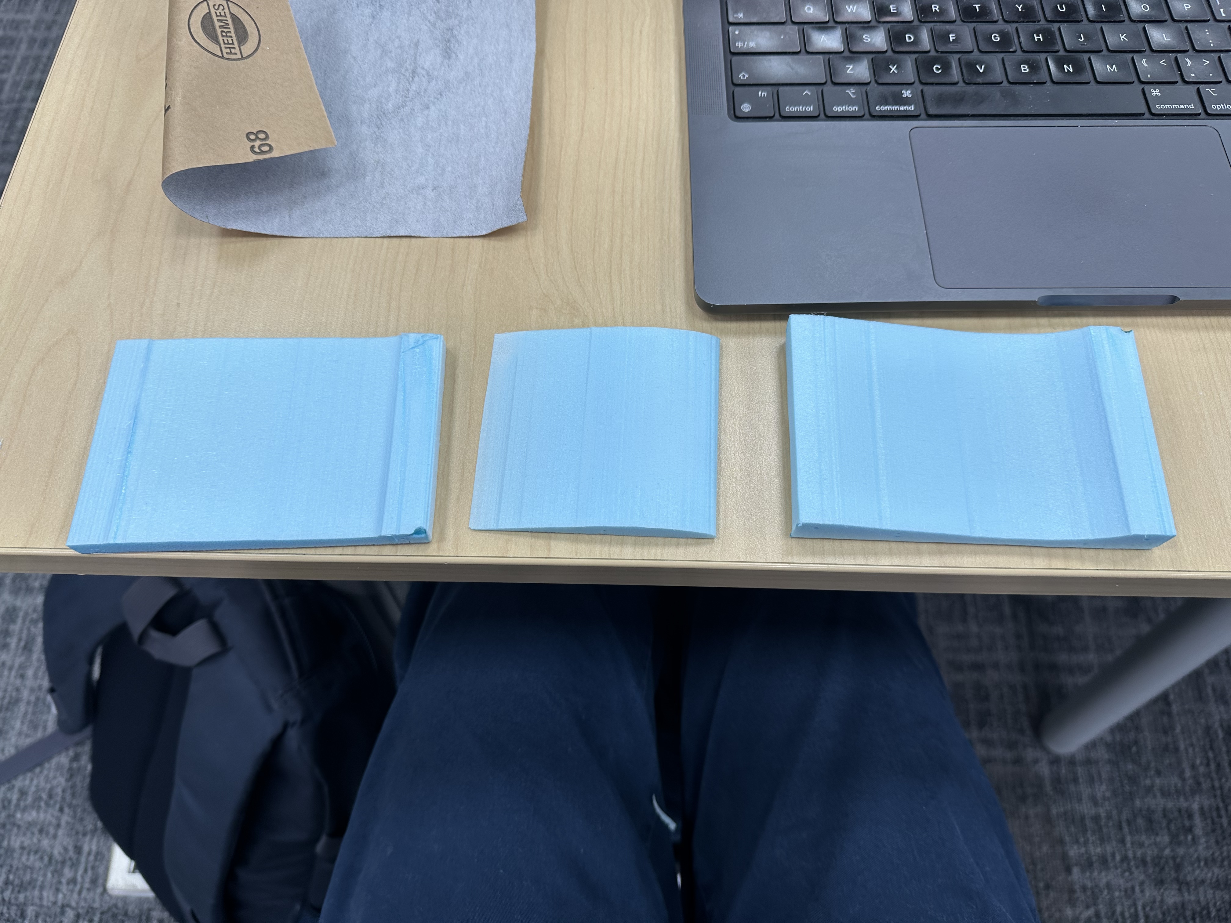
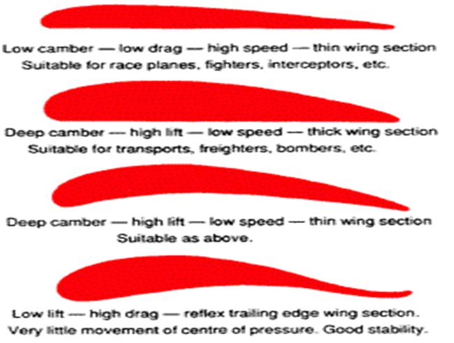
Different shapes depend on different shapes
Why would an airfoil create lift
A lift is a form of force
Throw a card
control the direction of going
A wrong theory (Equal Transit theory)
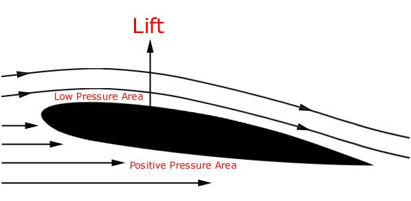
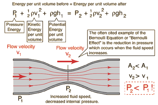
Burnouli’s principle
A particle from one place to reach another place in the same time
Some particles have a longer distance and travel faster
v1 > v2
p1 < p2
Force at the bottom is higher than at the top
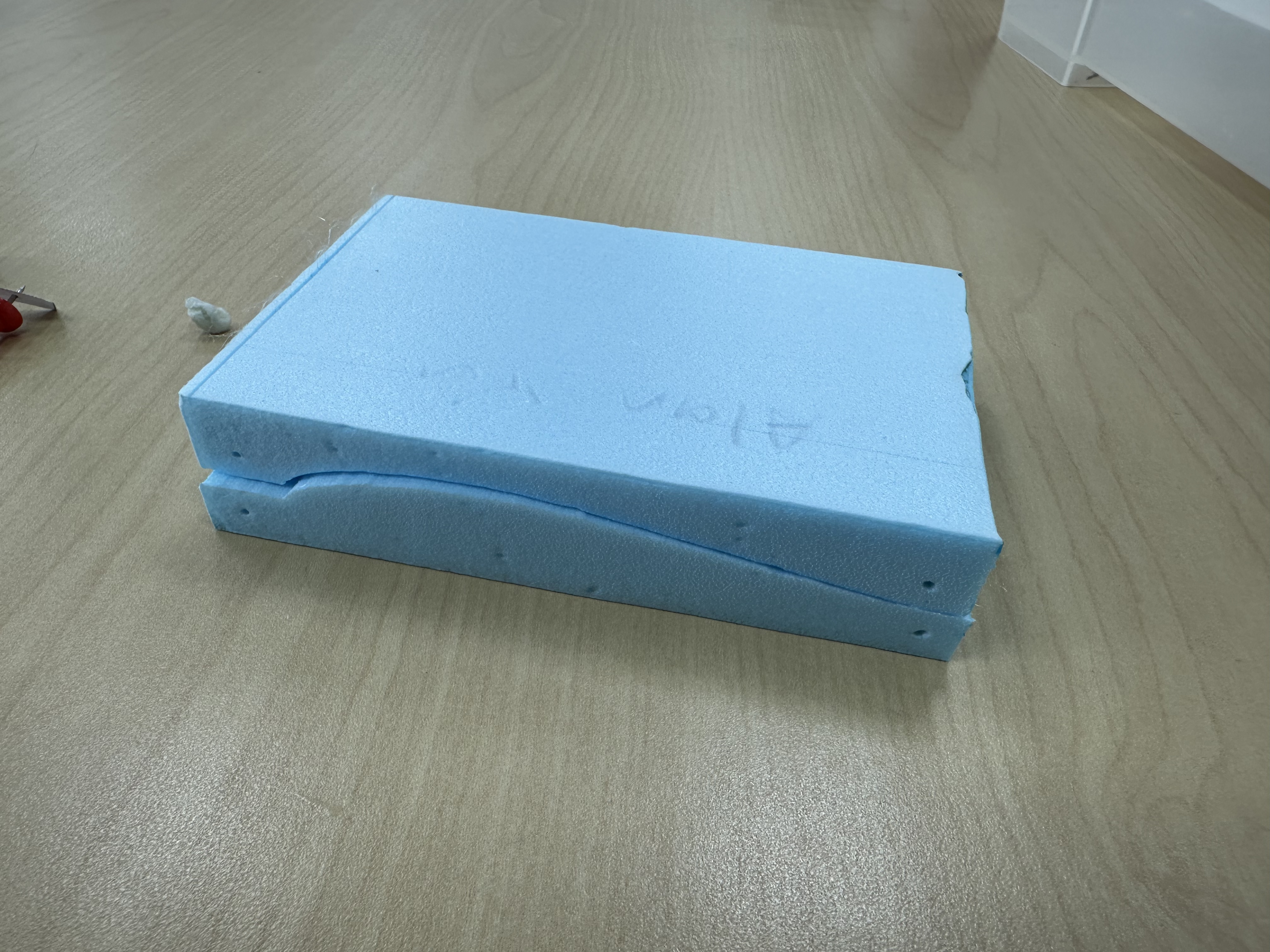
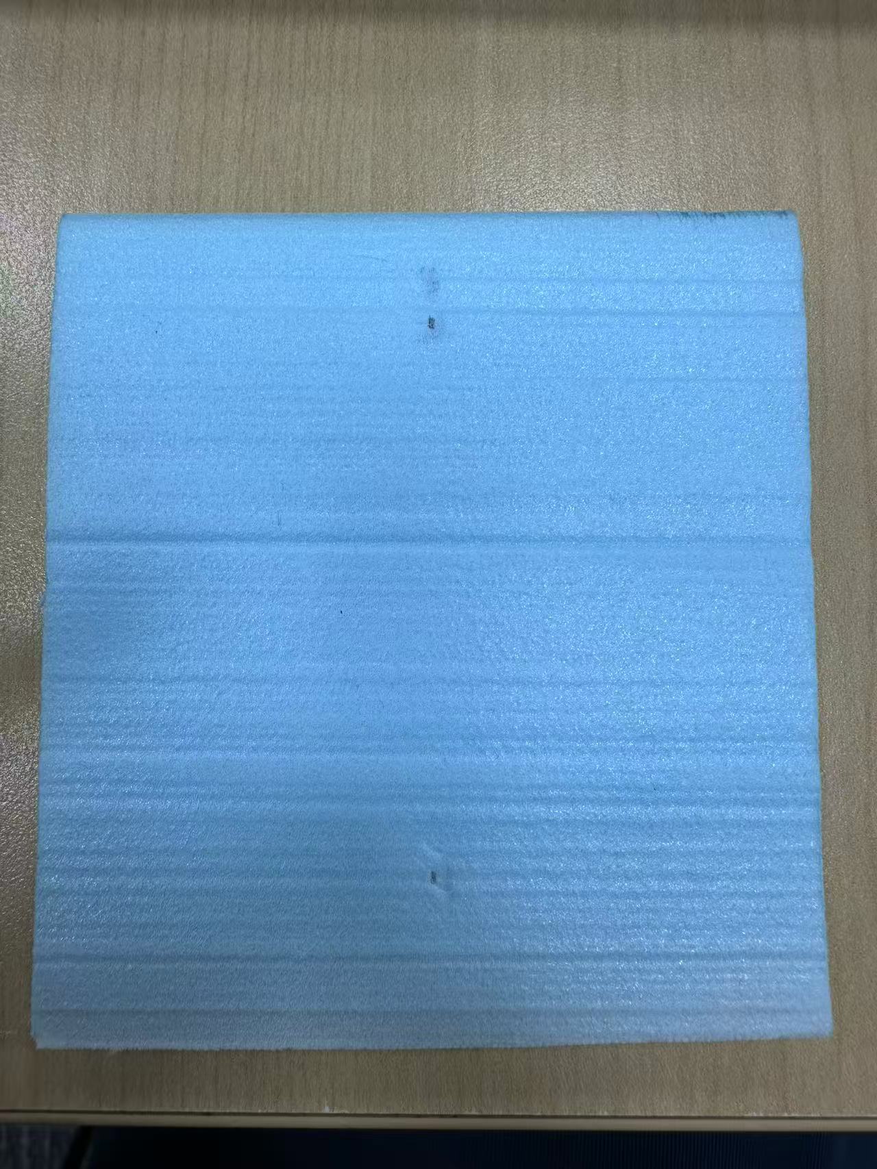
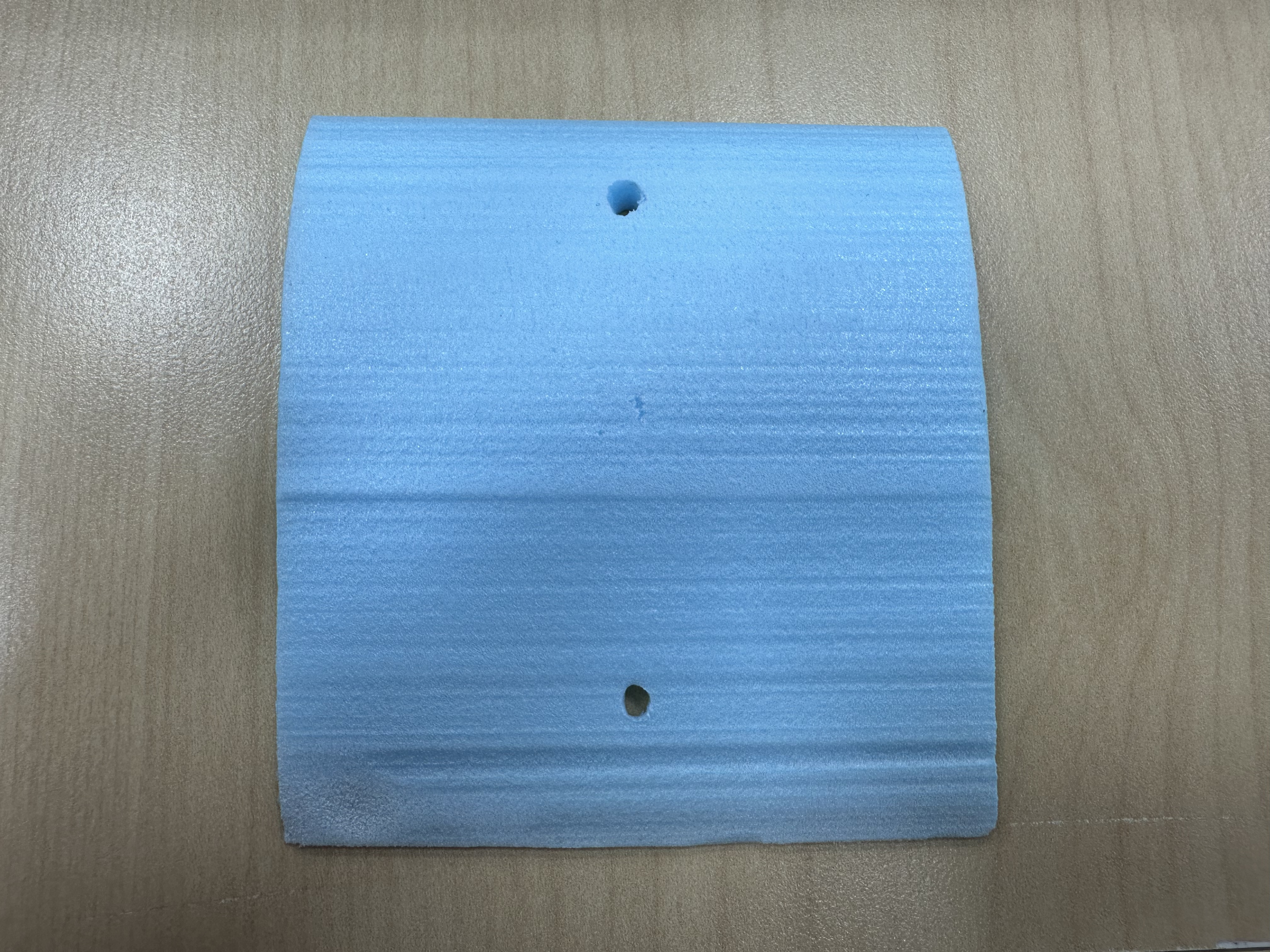
Balsa Plane with plain wings
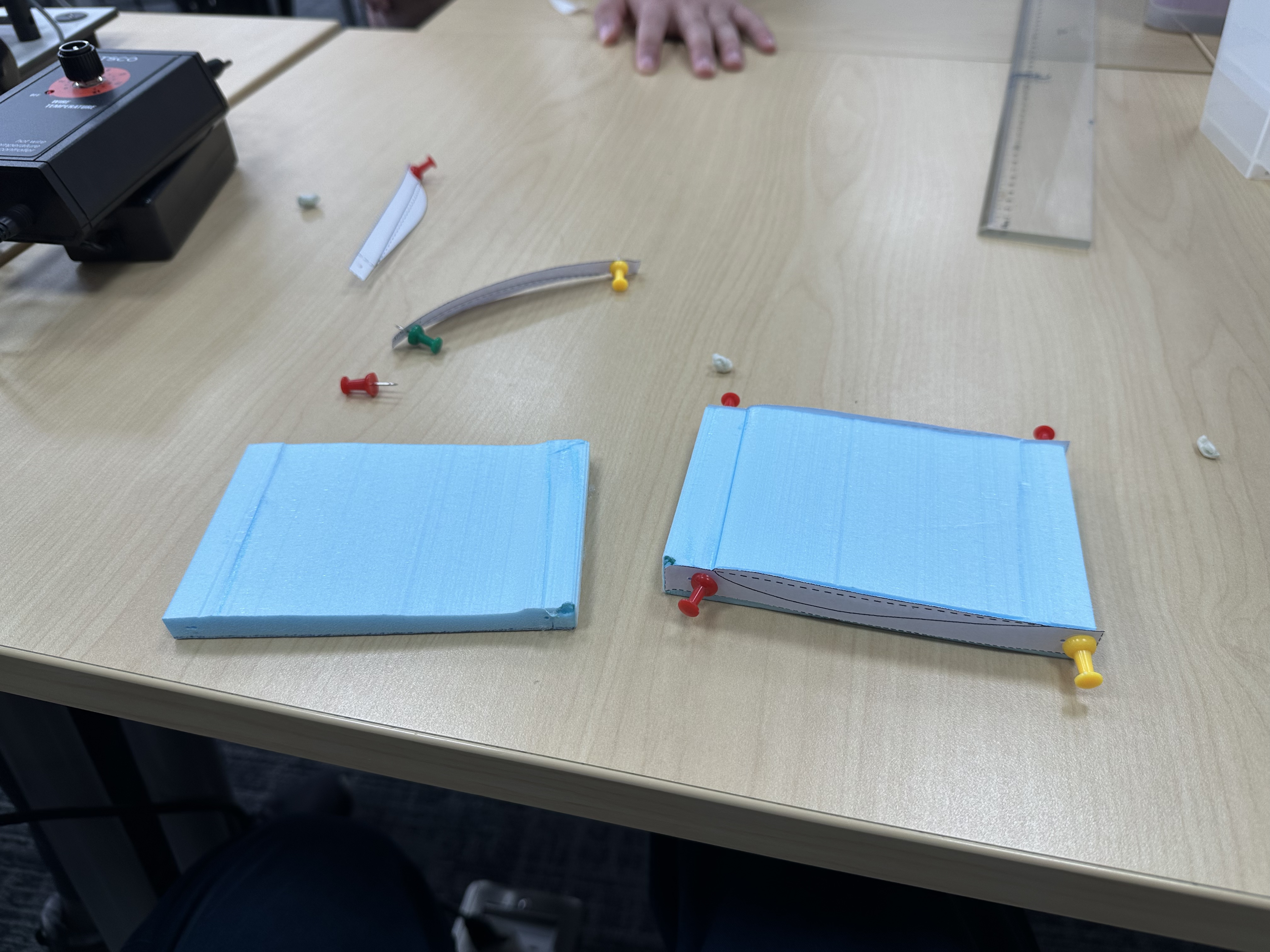
Flat means no difference in pressure and distance; where is the lift?
Birds fly with their wing of a circular movement
Curve down, swipe over.
Angle of attack
When swimming, swim a butterfly. Push forward
Some angle of inclination when an eagle attacks prey (It generates more lift)
Generate lift at a slower speed to make it easier to take off.
When an airplane was taking off, there was an extension of the curve at the back of the airfoil to generate more lift.
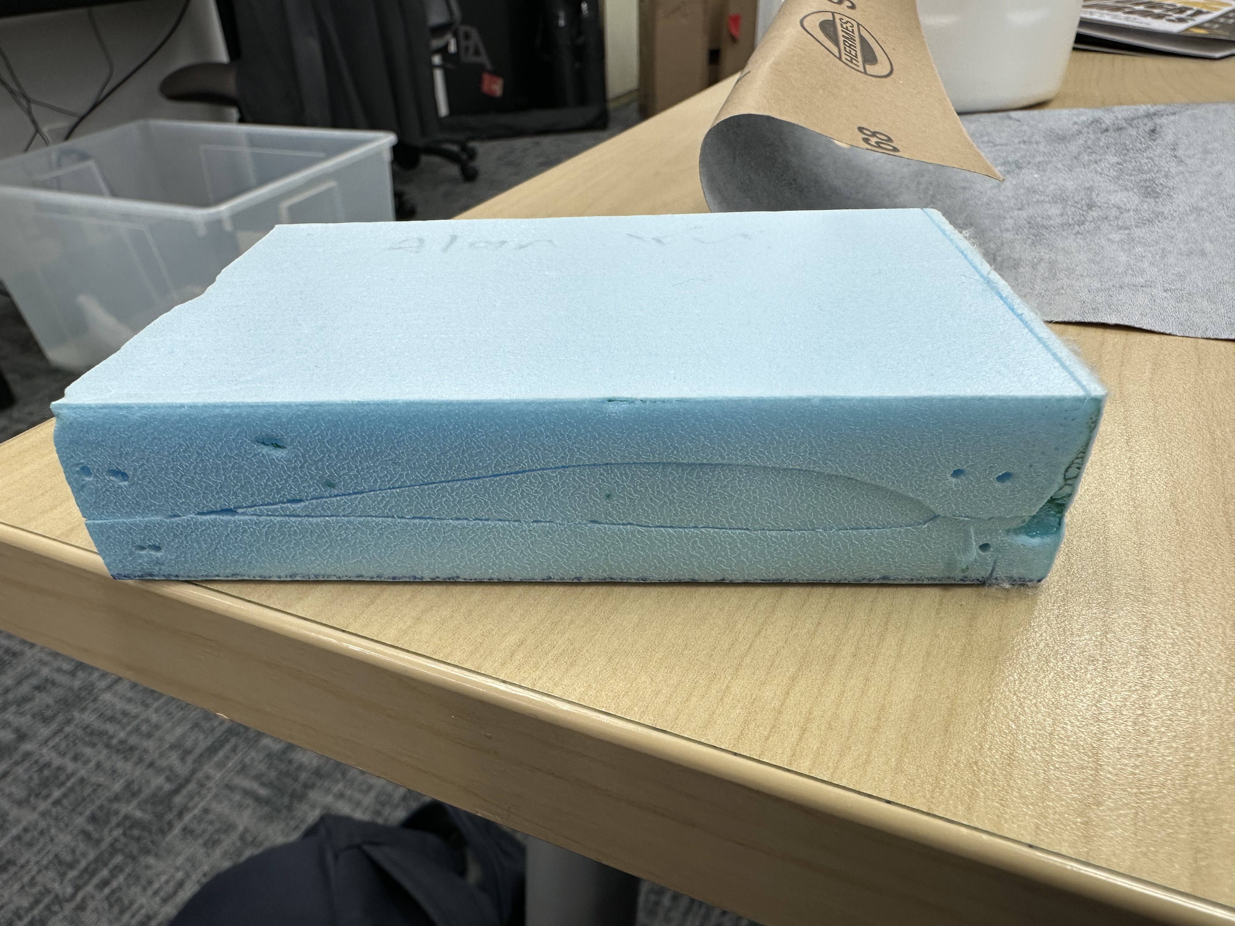
Airfoils
Some wings were swept back.
Applications
Windmails
Spoiler
Sails
Hydrofoils
Propeller piece
Spoiler of a car
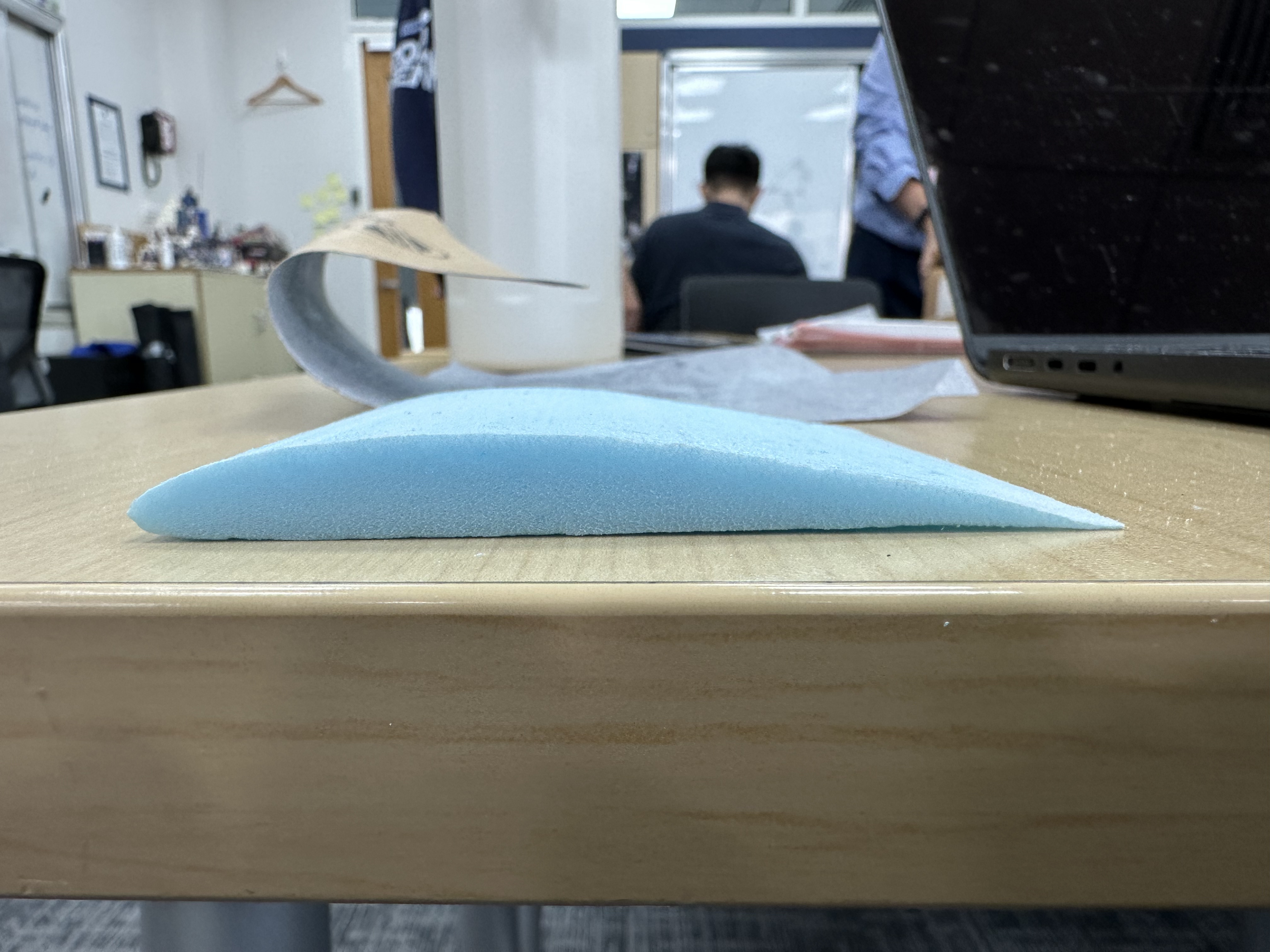
The curved part is the opposite of an airfoil
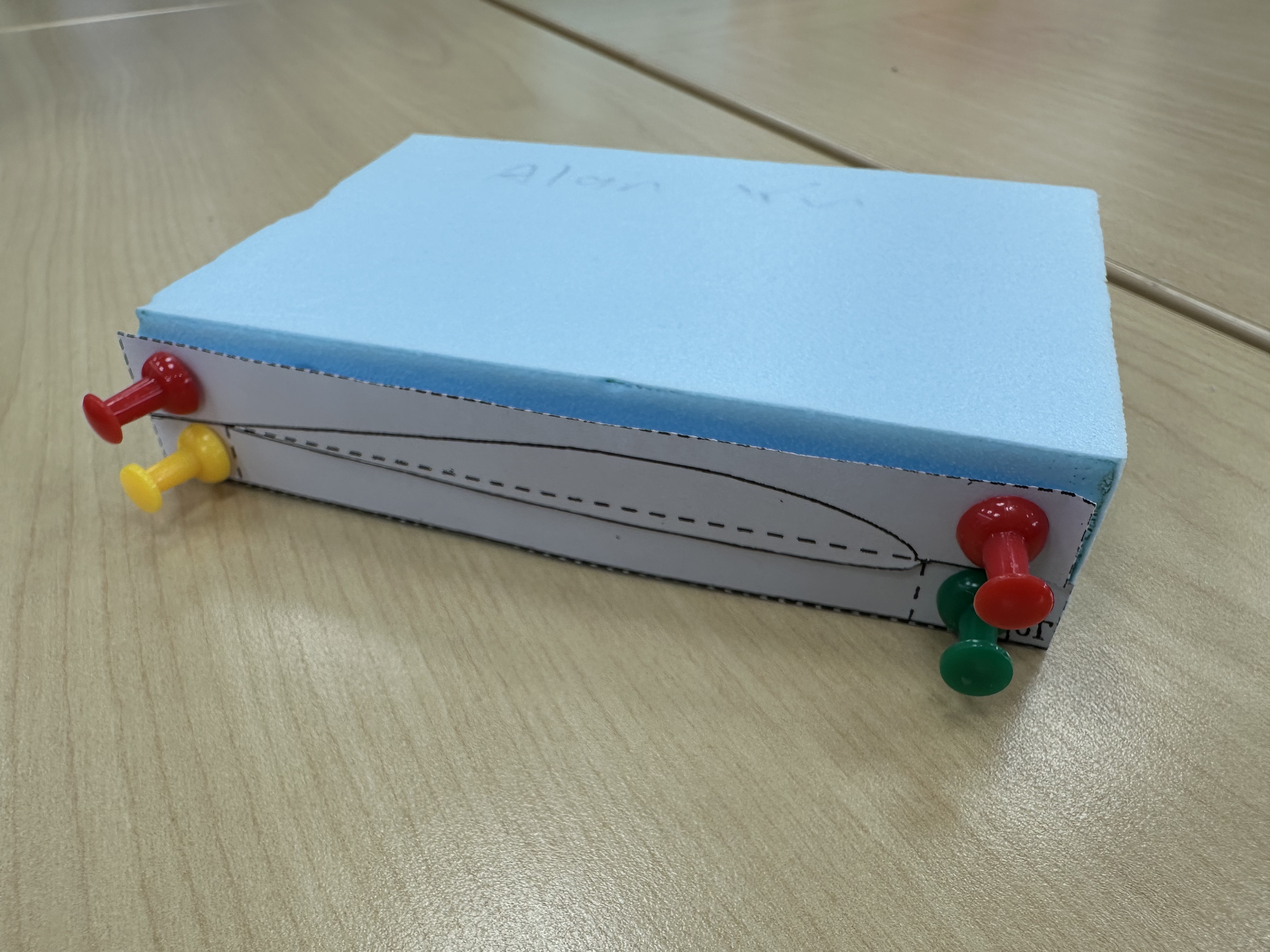
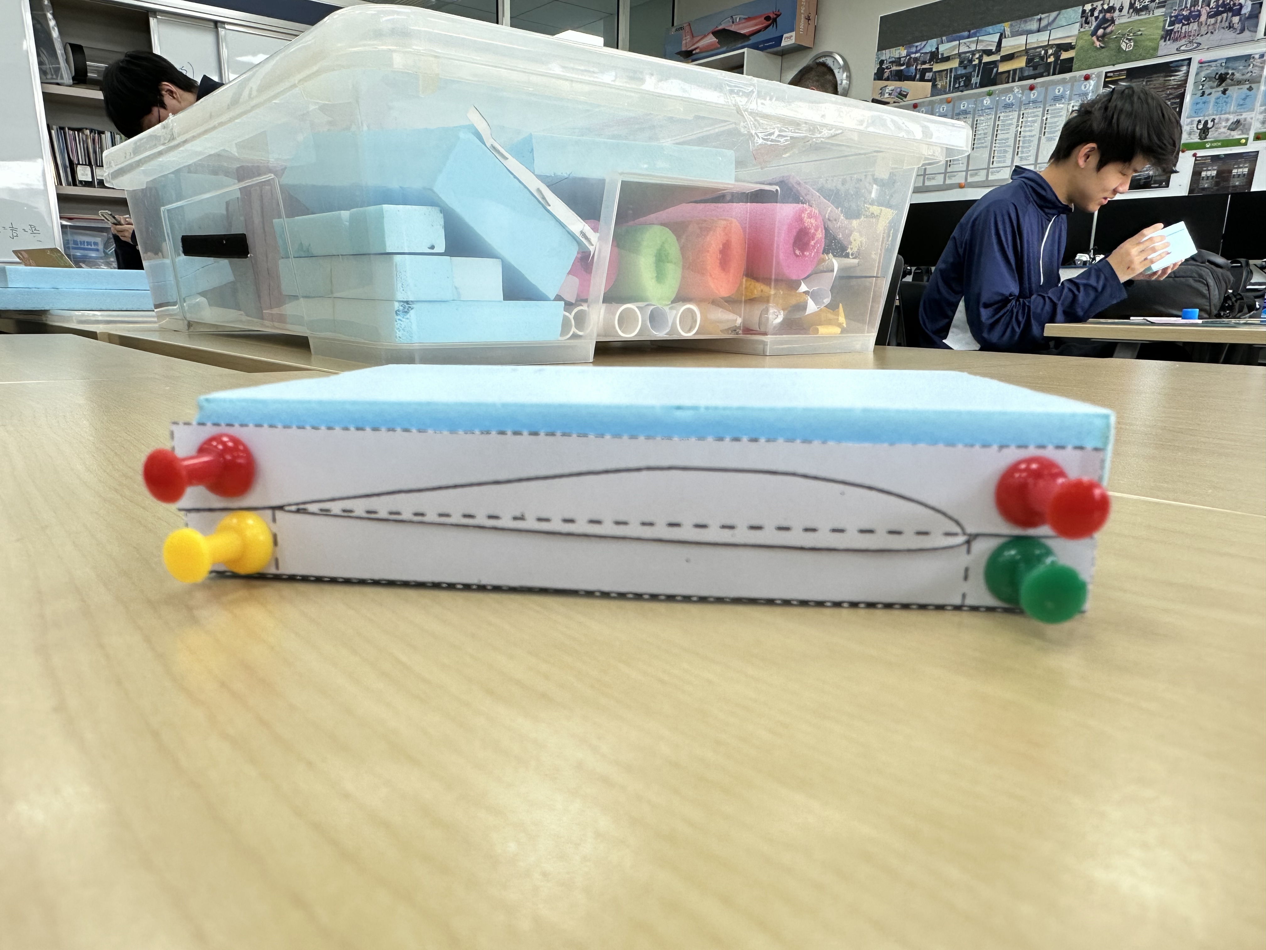
Parts
Chord line, Camber line, leading edge, max thickness, max camber, upper surface, lower surface, trailing edge
Leading edge: the section of the airfoil that meets the air first.
Trailing Edge: the section of the airfoil that meets the air last.
Upper Surface: The surface of the top wing
Lower Surface: The surface of the bottom wing
Angle of Attack (AOA): The angle between the chord line of an airfoil and the relative wind.
Depending on the AOA, life can increase or decrease.
Stalling: A sudden loss of lift and increase in drag at high AOA.
Usually 18 degrees
Air does not always flow uniformly (Turbulent flow, flow separation)
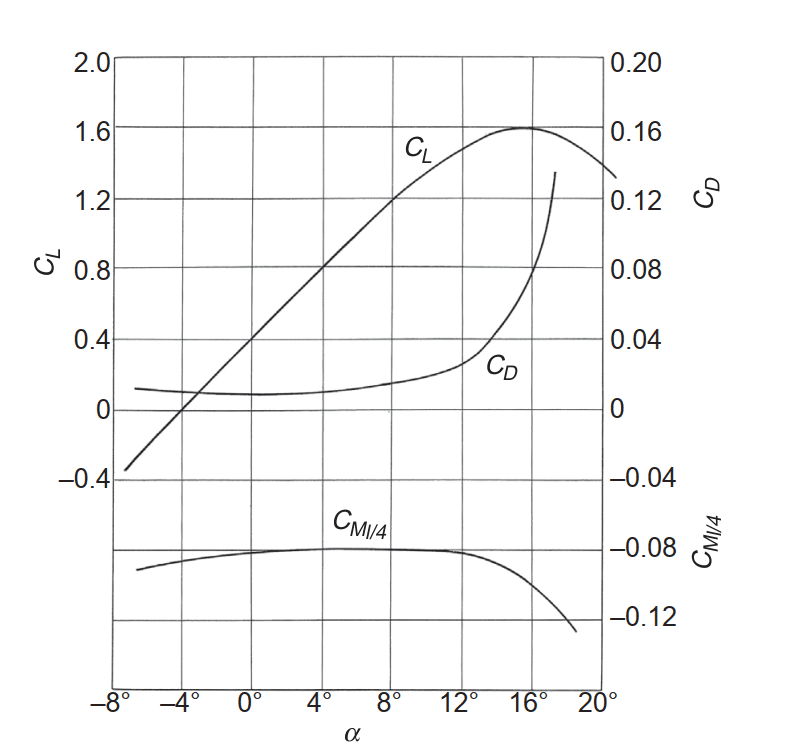
Graph showing the relationship of AOA with life and drag coefficient.
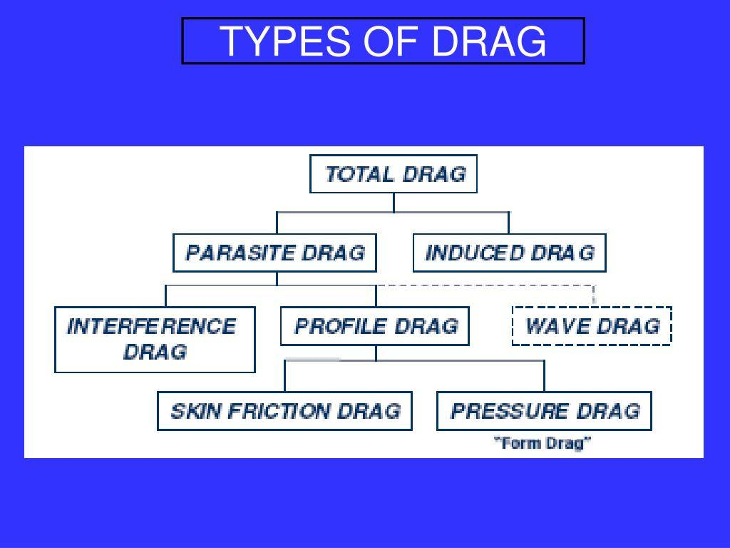
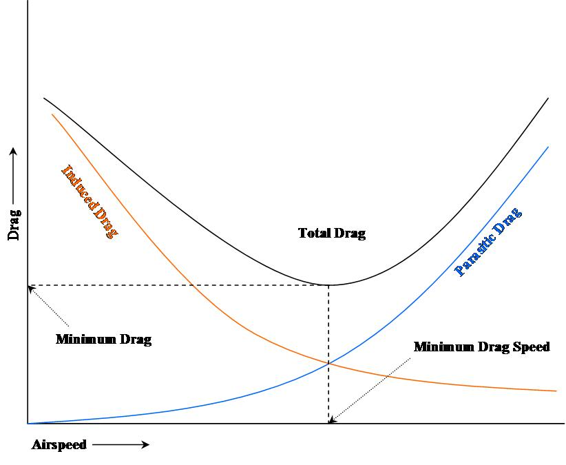
2 types of drag
Drag slows down the overall speed
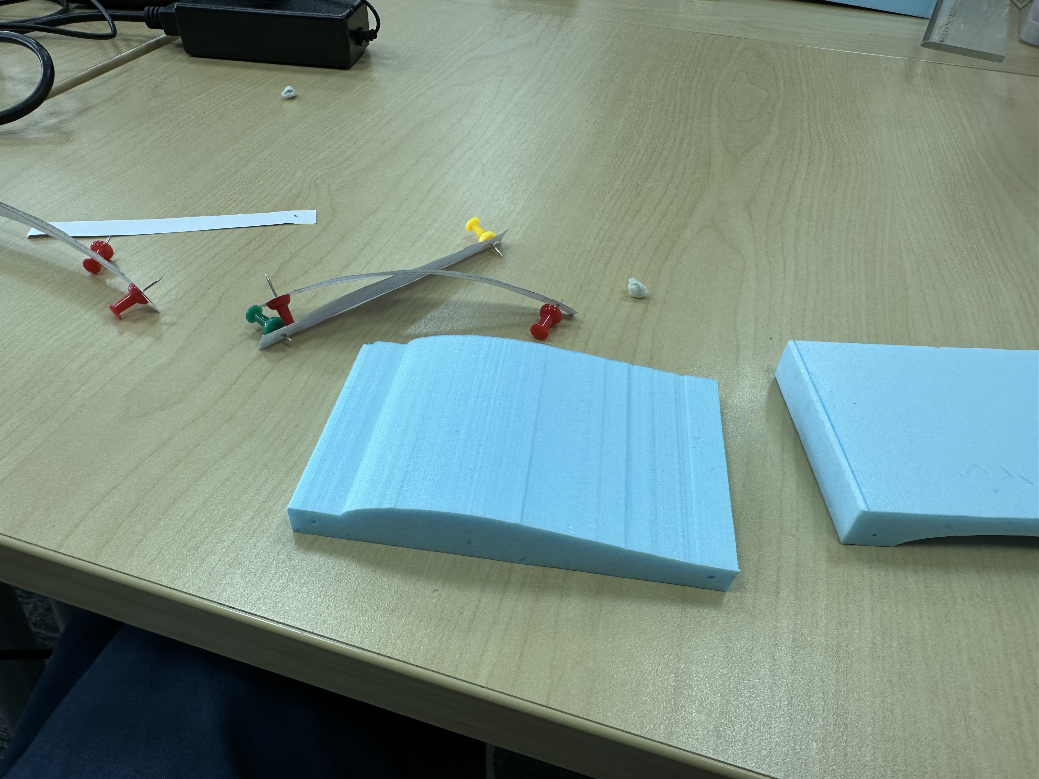
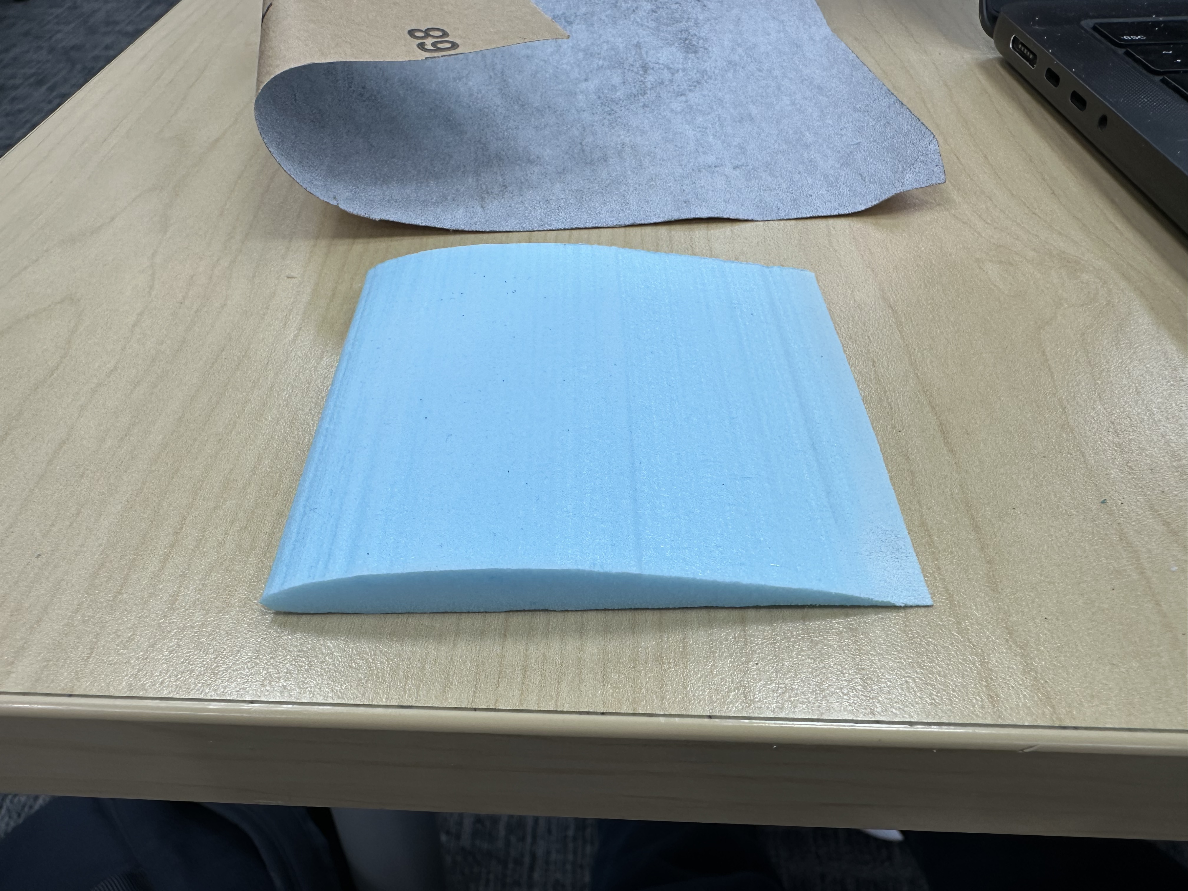
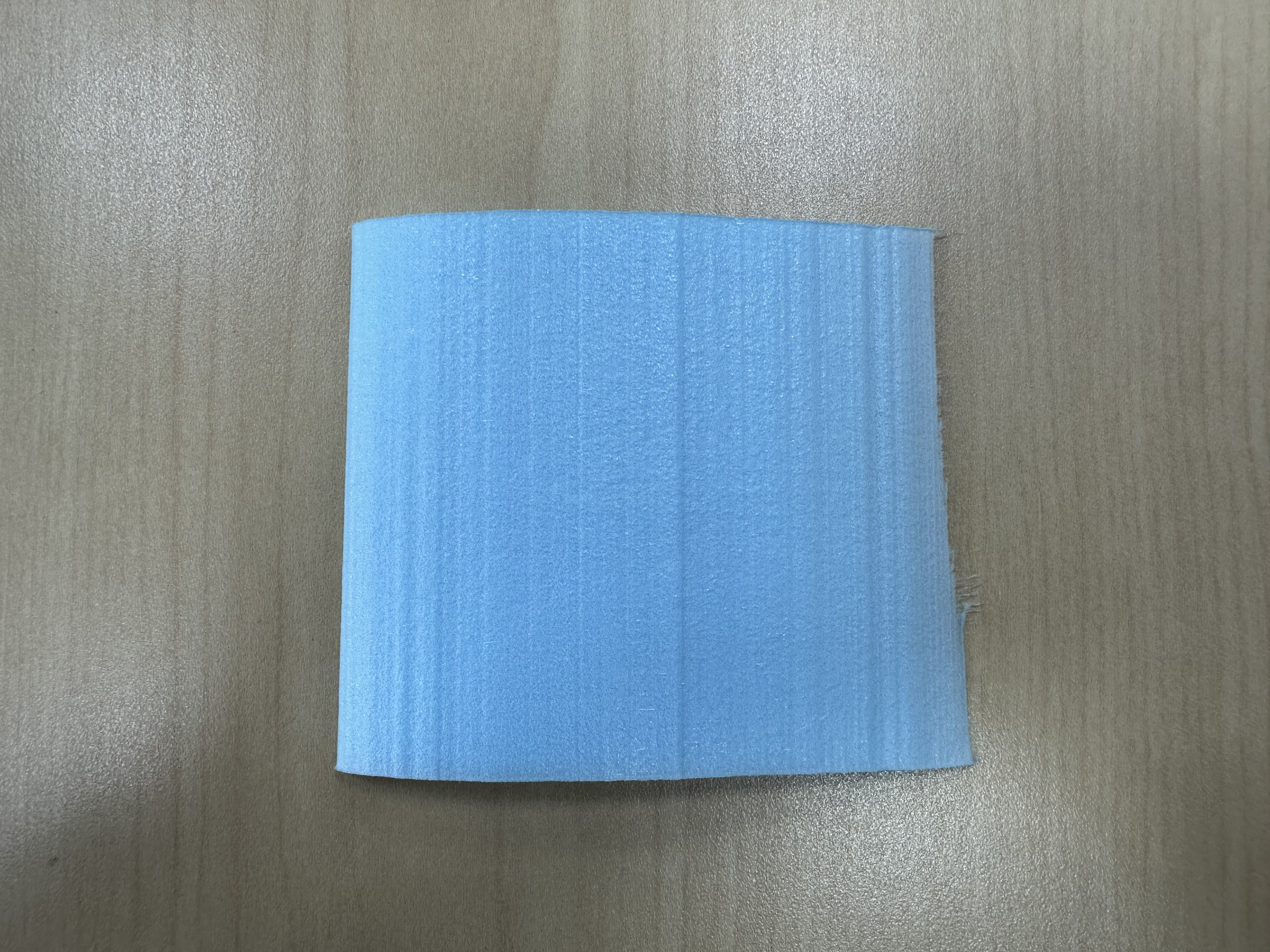
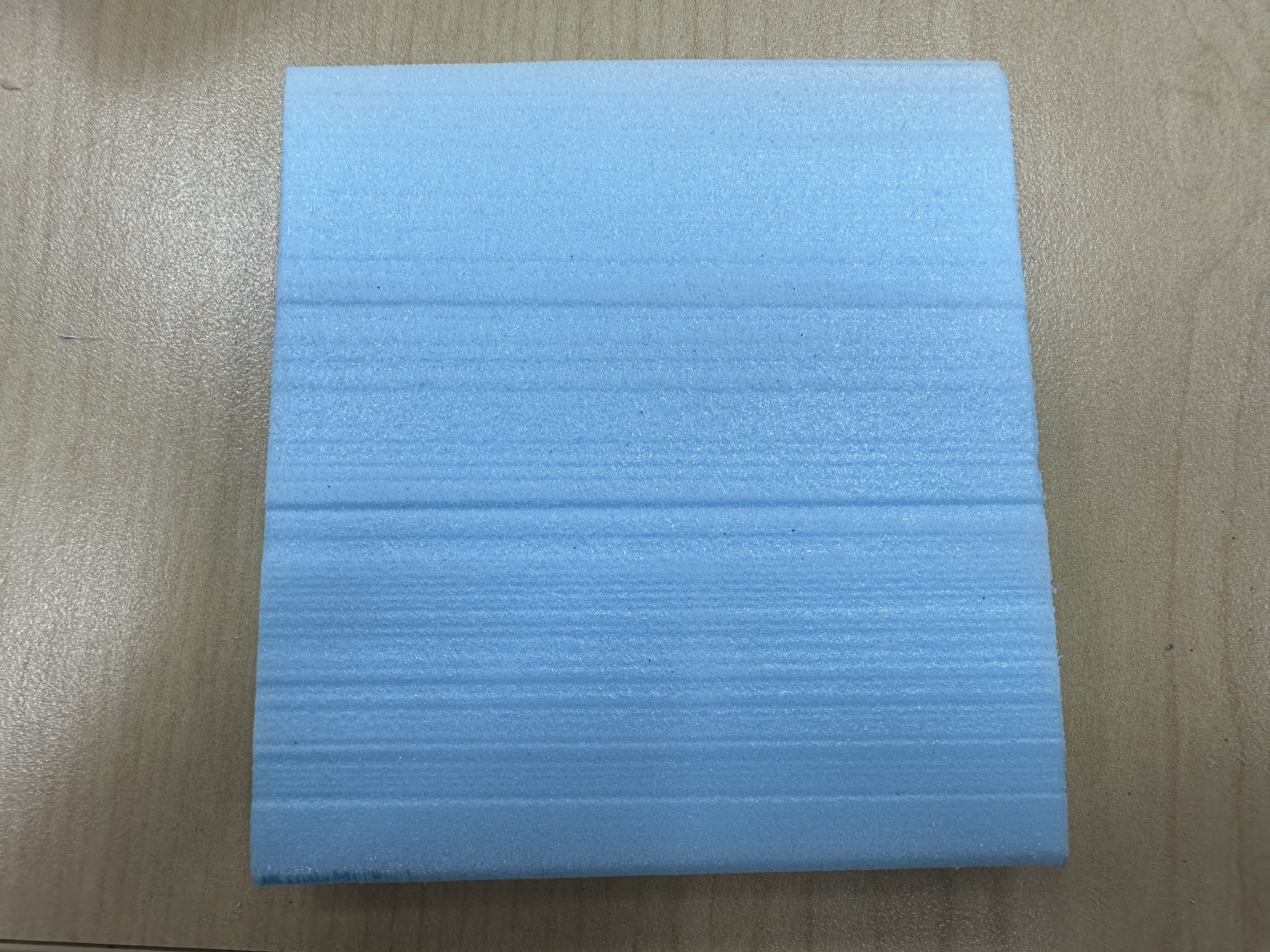
Why Curvature?
Generate Lift, the difference in pressure
The pressure at the bottom is higher, and the air flows faster at the top.
When squeezing a tube, the same amount of water should go through as well.
The speed of liquid flow is slower when large cross sectional area is large.
Imagine there’s a tube around the airfoil
Different species of fish have different shapes
Puffer fish. They are not aerodynamic.
Coanda Effect
Airfoil is 2D, Wing is 3D, has ends, and winglets.
Since a wing has an end, the air creeps up at the end and spirals backward.
Winglets typically reduce total aircraft drag by about 3% to 7% and, more specifically, can reduce lift-induced drag (vortex drag) by up to 20%.
Not increasing lift but reducing drag and safe feul.
Horseshoe vortex formation around a cylinder
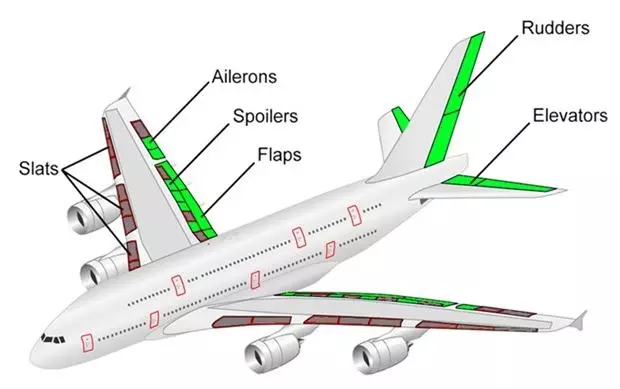
Controls the Roll when moving ailerons only
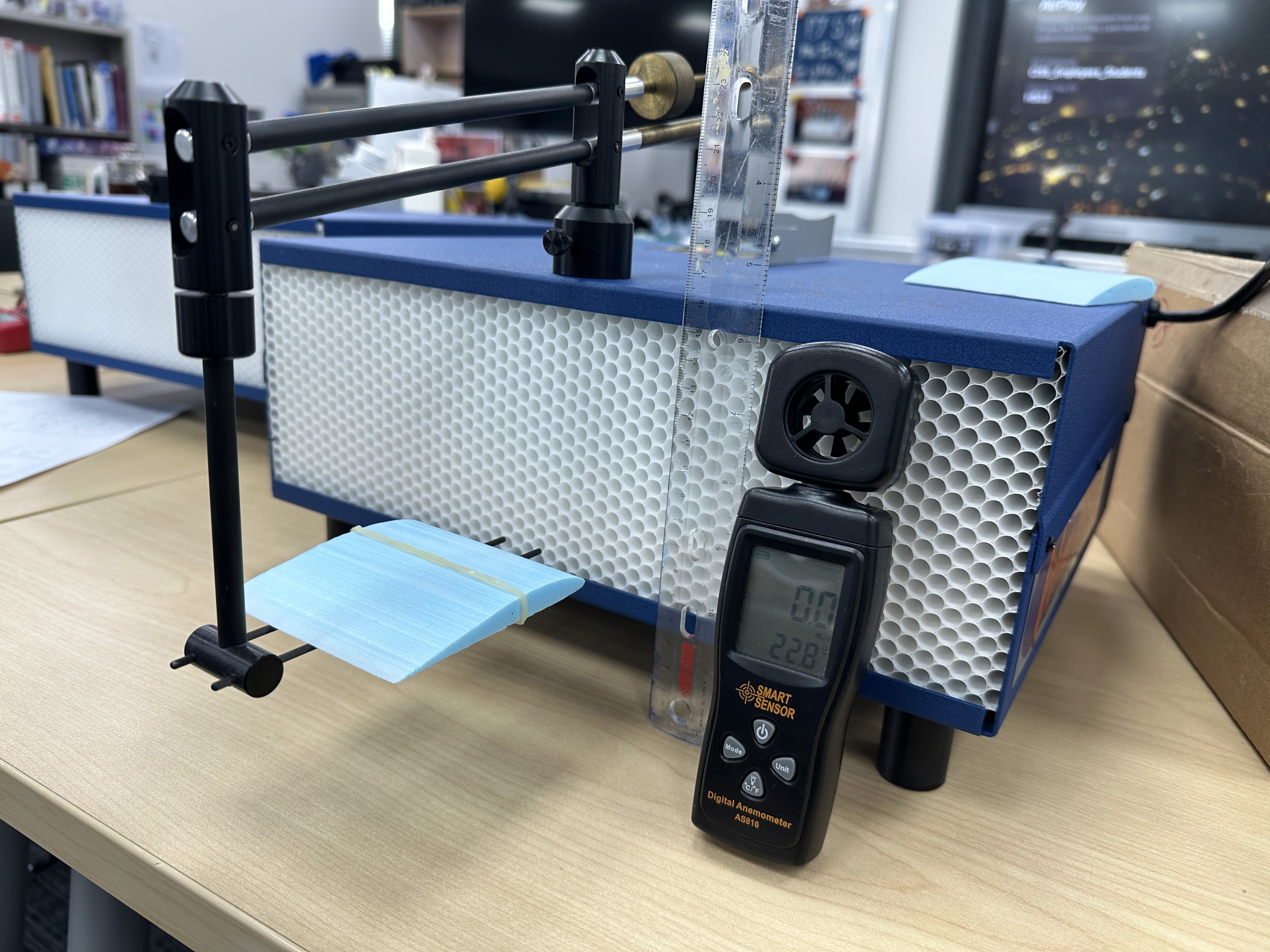
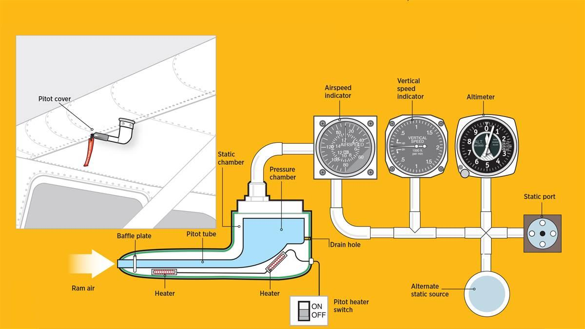
Pitot Tube

Bernoulli’s equation, , states that for an inviscid, incompressible, and steady fluid flow, the total energy along a streamline remains constant. It represents the sum of static pressure (), dynamic pressure (), and hydrostatic pressure (), where higher velocity equals lower pressure.
Key Components and FormulaThe equation relates pressure (), fluid density (), velocity (), gravitational acceleration (), and elevation () at two points (1 and 2) along a streamline:
- (Static Pressure): The actual thermodynamic pressure of the fluid.
- (Dynamic Pressure): Kinetic energy per unit volume.
- (Hydrostatic Pressure): Potential energy per unit volume due to gravity.
Already know the pressure of the air at a certain alttitude
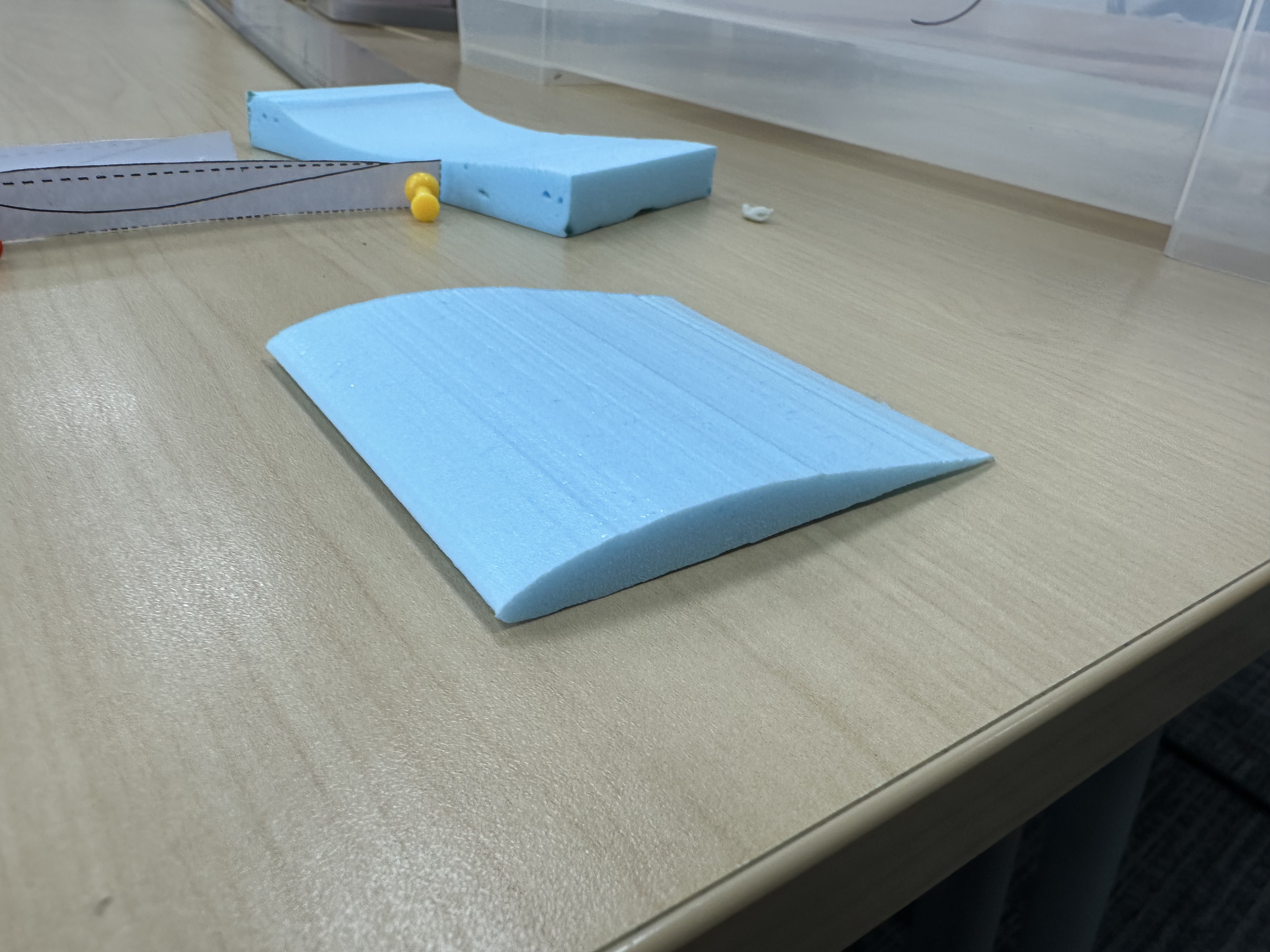
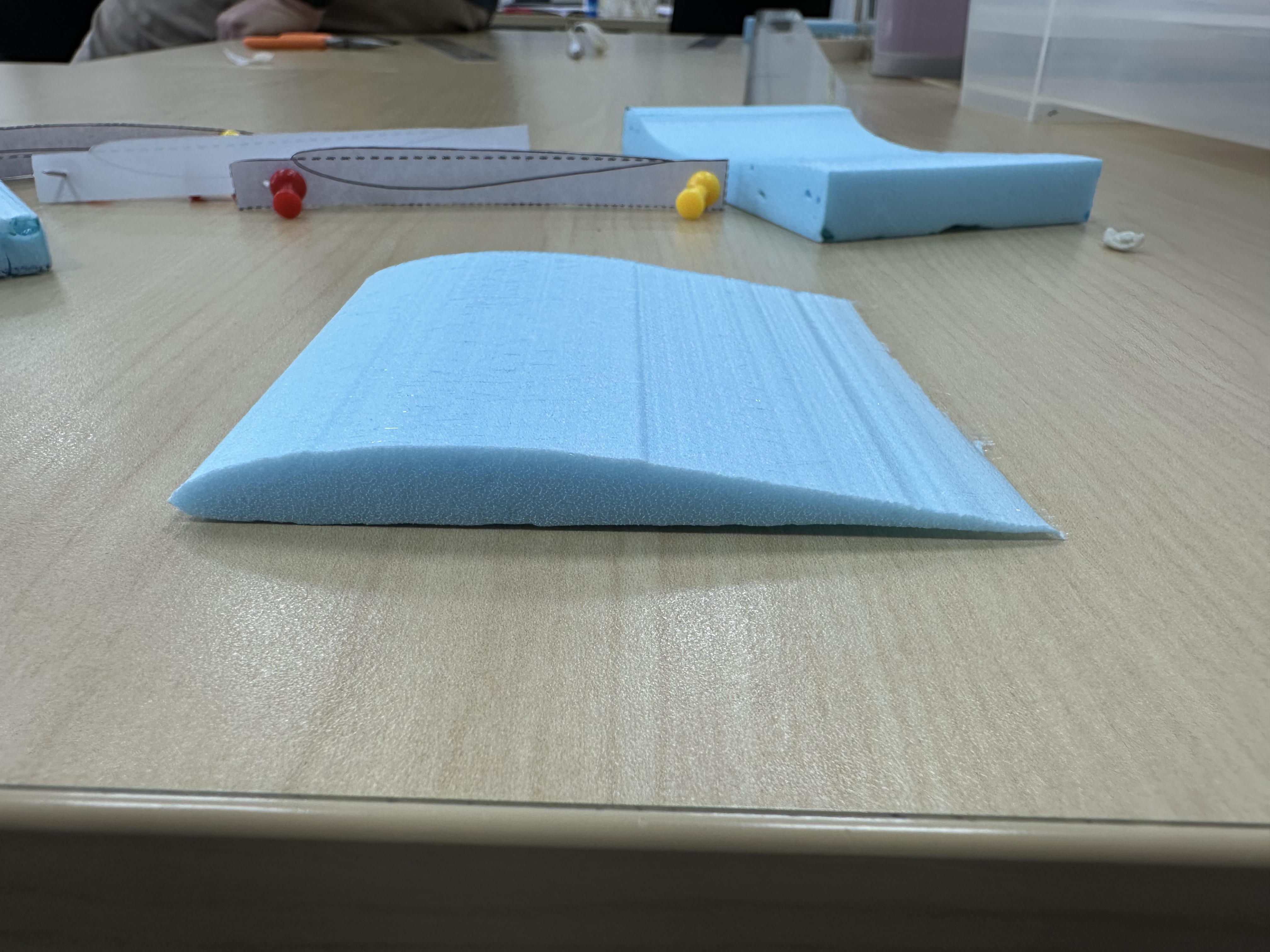
Design
Objective:
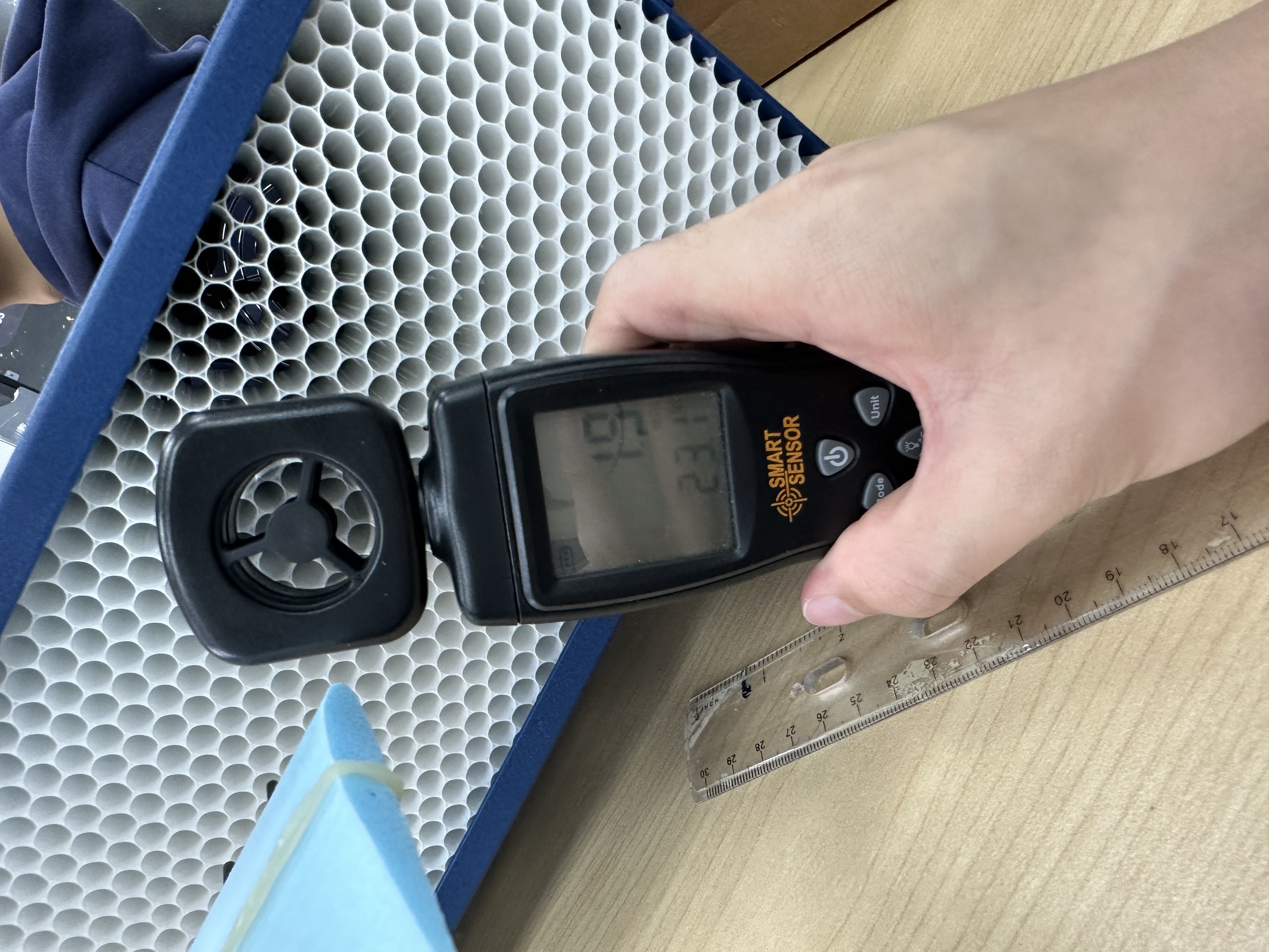
The aircraft in question is a small powered model airplane with cruise speed of approximately 5 m/s and a chord length of approximately 10cm. The main focus is the maximum lift-to-drag ratio for range and glide efficiency.
Reynolds Number
Since we are in Shanghai, the Reynolds number was computed using standard sea-level conditions with air kinematic viscosity .
This places the aircraft firmly in the ultra-low Reynolds number regime (Re ~ 3.3 × 10⁴), where laminar separation bubbles dominate airfoil performance and airfoil selection becomes critical. In this regime, most conventional airfoils designed for higher Reynolds numbers perform poorly due to extensive laminar separation and transition-related losses.
Four airfoils were evaluated based on published low-Re wind tunnel data from the UIUC Low-Speed Airfoil Tests and their suitability for the stated design mission:
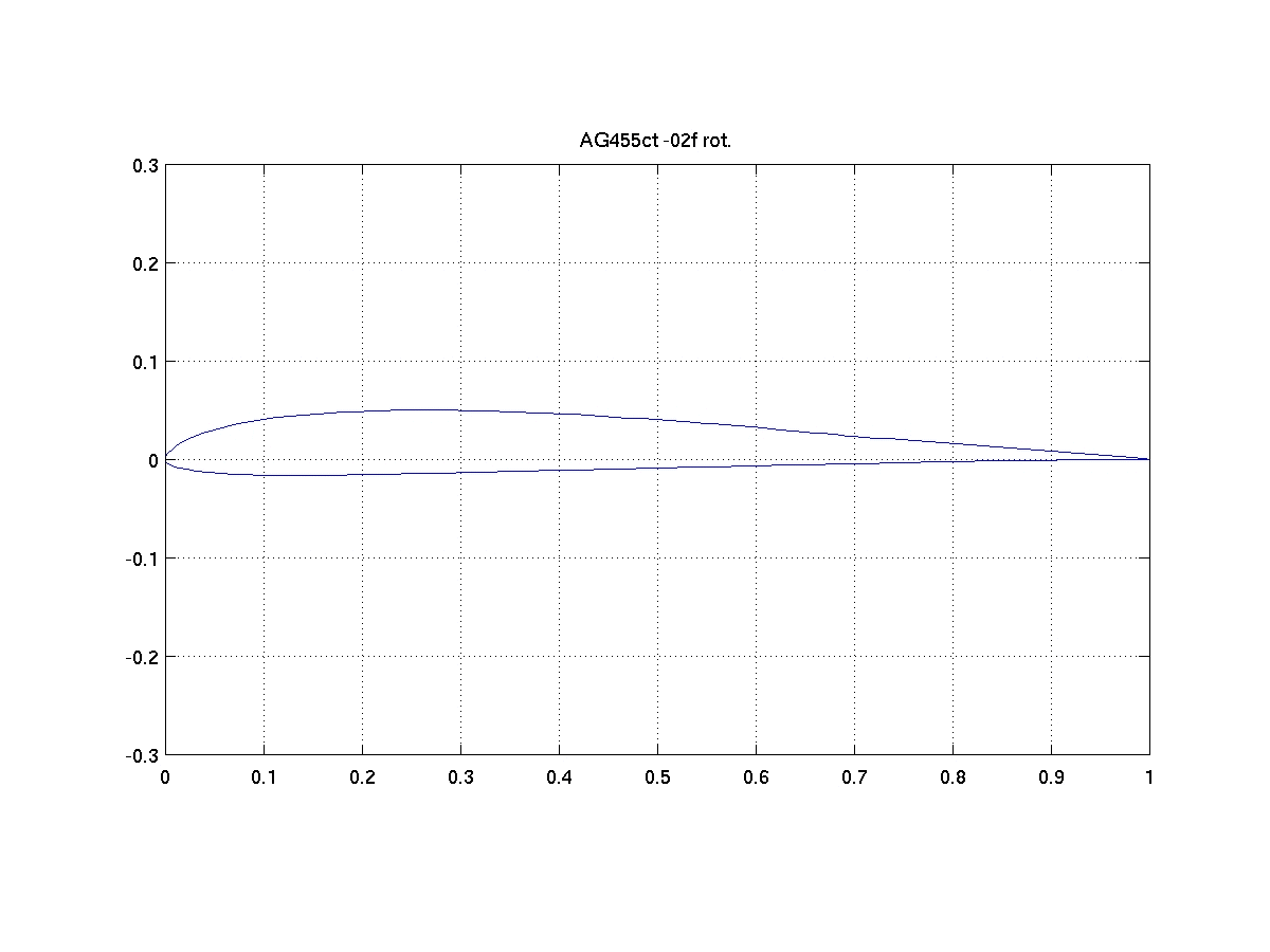
AG455ct (Mark Drela) A purpose-designed ultra-low Reynolds number airfoil from the AG series. At Re ~ 3 × 10⁴, it maintains effective laminar separation bubble control and achieves a lift-to-drag ratio in the range of 30–40, which is excellent for this Reynolds number regime. Thickness is approximately 7.6% chord with moderate camber. This airfoil is optimized precisely for the conditions of this design mission.
Clark Y
E-205
E-214
E-387
Linder