This is an assignment on a powered balsa propeller airplane in aerospace for the AL Aerospace Engineering course at Concordia International School, conducted by Dr. Peter Tong (aka D.T). This article documents how I designed, built, and tested a powered balsa wood airplane that flies in a circular trajectory as an exploration of physics phenomena throughout the building process.
This article walks through how I designed, built, and tested a powered balsa wood airplane that flies in a circular trajectory as an exploration of physics phenomena throughout the building process.
Objectives
To build a stable powered airplane that can sustain flight (and not stall) continuously in a circular path.
Guiding Questions
- What is the effect of the position of the propeller?
- How can the aircraft be controlled to make sure it does not pitch down too much, which might cause a stall?
- What attachment method can be used to mount heavy components, such as the motor, to the fuselage to ensure a strong and stable structure under takeoff and landing loads?
- What is the relationship between nose-up pitch angle on the ground and the subsequent vertical component of the flight trajectory after launch?
- How can the undercarriage be designed to keep the angle of attack manageable at takeoff while still enabling a stable landing?
Materials
- Balsa Sheet (1.5×75mm × 915mm) (1 pc)
- Balsa Strut (5×5×50mm) (1 pc)
- Motor with Propeller (1 pc)
- Hot Glue / Wood Glue / Super Glue
- Tape
- Cutting knife
- Ruler
- Cutting board
The plane is again built from balsa wood, chosen for its strength-to-weight ratio as discussed in the previous article. But with a motor and propeller now on the nose, the structure has to deal with a lot more stress than a simple unpowered glider.
Design and Construction
Initial Configuration
The powered version started with the same basic shape as the unpowered glider from Part 2. The main differences were a motor with a propeller on the nose and a front wheel pair as landing gear. Here are the starting dimensions.
- Wing:
- Horizontal Stabilizer:
- Vertical Stabilizer:
- Landing Gear (front wheel): single axle, approx. vertical height
For the motor, I just glued it onto the nose using wood glue. The front wheel was glued to the bottom of the fuselage with superglue. Figures 1 through 3 show what the initial design looked like.
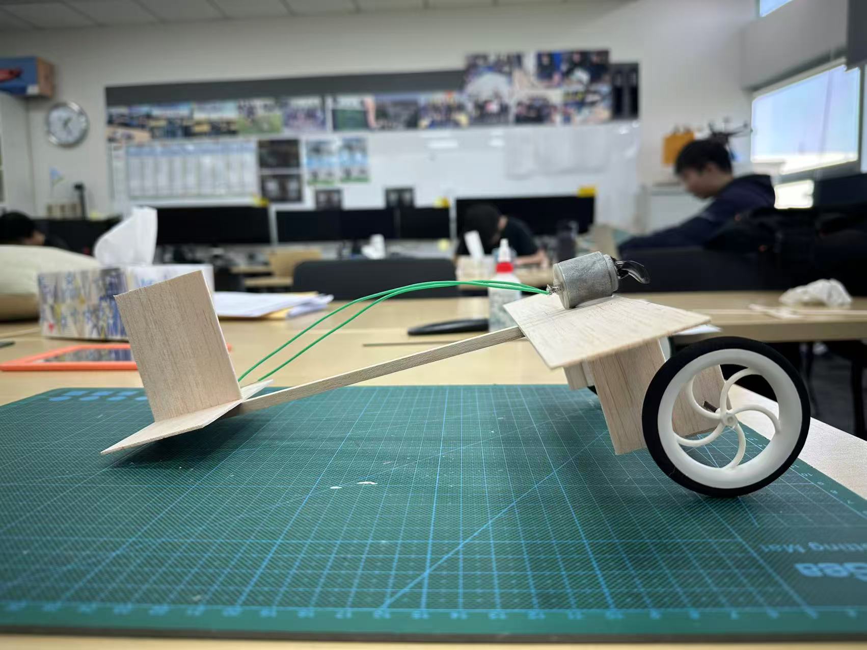
Figure 1: Initial Design (Side View) 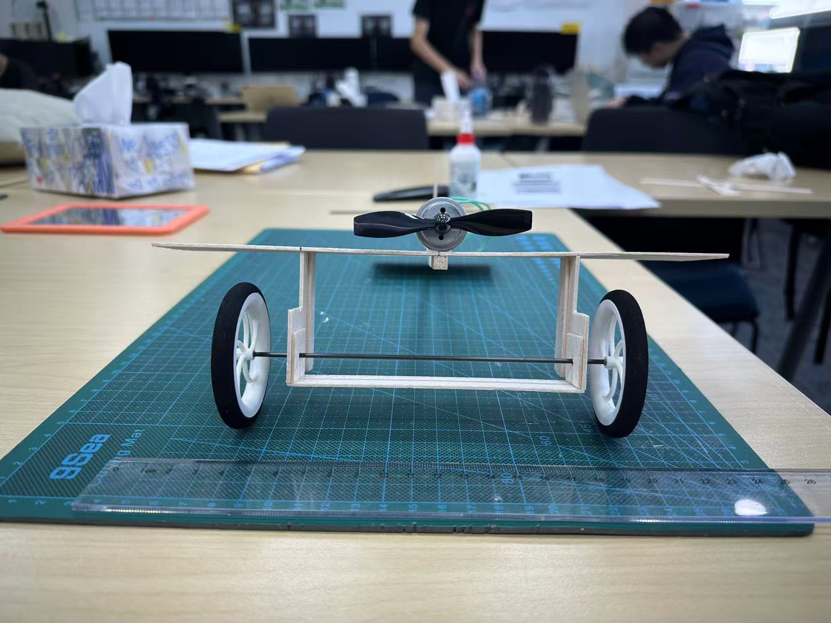
Figure 2: Initial Design (Front View) 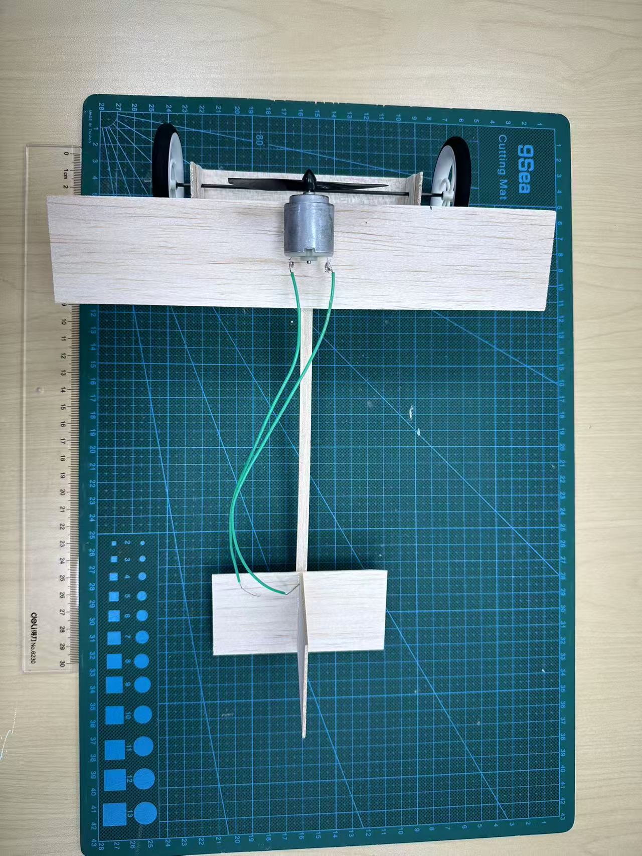
Figure 3: Initial Design (Top View)
Ground Angle of Attack and CG Relations
One big thing I didn’t think about at first was how the landing gear height affects the angle of attack at takeoff. The front wheel sat about 5.5 cm off the ground, and nothing was supporting the tail. So the whole plane just tilted nose-up pretty much, with the tail touching the ground. As shown in Figure 4, the center of lift shifts gradually forward as the angle of attack increases.
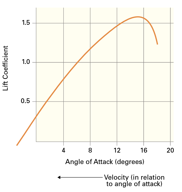
Figure 4: Center-of-lift position as a function of angle of attack.
As the initial angle of attack increases, the center of lift shifts further forward, eventually exceeding the center of gravity. This produces a nose-up pitching moment that further increases the angle of attack. In a circular flight path, this loop causes the aircraft to become unstable and significantly increases the likelihood of a stall.
This design is absolutely problematic. As shown in Figures 5 and 6, A steep nose-up orientation causes the flight to depart with a high vertical acceleration driven by thrust. As the flight is not able to correct itself, if this angle exceeds a certain critical angle of attack, the wing stalls almost instantaneously after the aircraft leaves the ground (Anderson, 2016). This is worse in a circular path, while a string is dragging the flight to the center of a ball, as if the flight keeps elevating, it will be pulled back to the ground and cause a stall.
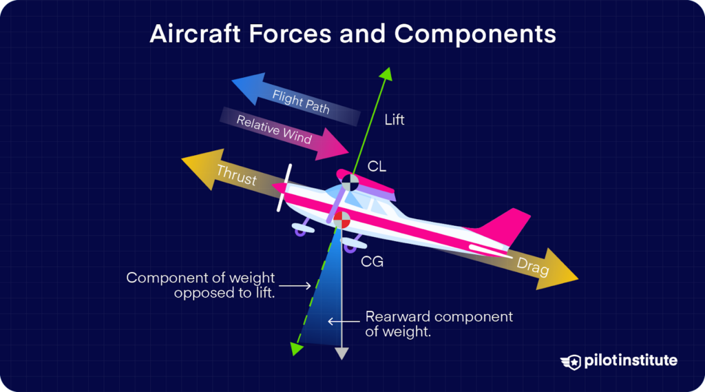
Figure 5: Aircraft Forces and Components.
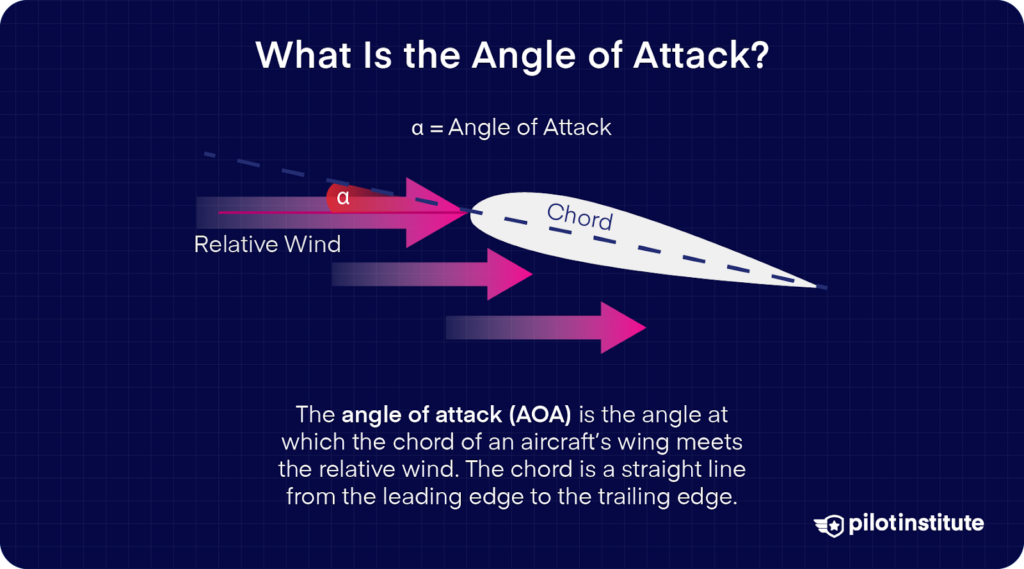
Figure 6: Description of Angle of Attack.
This effect depends on the relationship between the ground-imposed pitch angle and the CG position. When the CG is aft of the main wing’s center of lift, the nose-up ground angle increases the pitch-up tendency, because the aerodynamic moment about the CG is not strong enough to restore the initial nose-up attitude. In contrast, a more forward CG would provide a greater restoring pitch-down moment and abate this problem. However, in the initial configuration, the tall front landing gear system made the ground pitch angle so high that even a significantly front CG still could not reduce it properly.
Flight Testing and Iteration
Trial #1
Figure 7 shows the whole structure of this flight before the 1st trail. The aircraft was tethered to the machine in the center and powered by a powerful power source. Once the power was turned on and the motor was powered, the plane actually lifted off for a while, but it pitched up almost immediately and crashed into an obstacle. The front wheel snapped off the fuselage entirely, and the motor came off the nose too. The plane was completely broken.
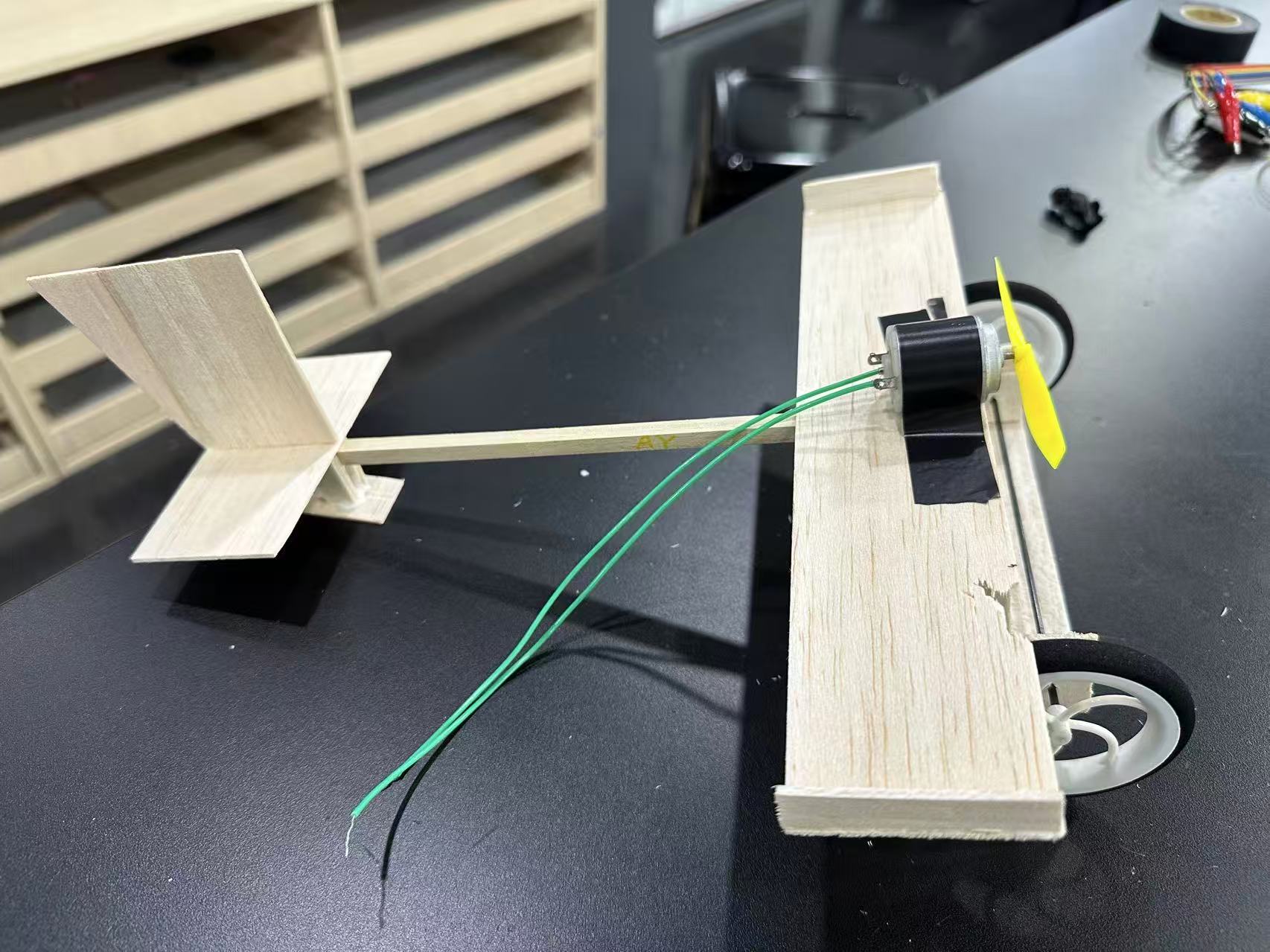
Figure 7: 1st Trial
Analysis
The aerodynamic problem was basically what I already realized, which is the thing about the Ground Angle of Attack. The front wheel was so tall that the plane sat at a really steep angle on the ground, just as I mentioned before. The moment the motor pulled the plane forward, and it lifted off, the wing was already past its critical angle of attack. So instead of accelerating and gaining lift normally, the plane just pitched up further abnormally and stalled.
Aside from that, the structural design of this flight had another significant problem as well. At first, I had glued the wheel strut to the bottom of the fuselage with wood glue, but the contact area between the strut and the balsa was only a section of a tiny piece of balsa wood, approximately less than one square centimeter. Wood glue is fine for normal wood-to-wood joints with a decent surface area, but with that little contact, there’s basically nothing holding it. The moment the plane hit the ground, the joint just popped because of the instant high momentum exerted on the flight(Soden & McLeish, 1976).
The connection made between the fuselage and the motor also had a problem while I had attached the motor to the nose, only using a single section of tape. Firstly, the tape doesn’t work well on a wooden surface as it cannot provide enough strength with a larger surface area. The second thing is that I only made one section directly stick to the surface without any wrapping. I underestimated the amount of force the flight would suffer, and the motor was actually vibrating constantly while spinning the propeller. When the crash happened, the tape peeled off, and the motor finally flew off the body.
Improvements based on mistakes
After that, I realized that the landing gear (Undercarriage) system was actually useless. It only helps to reduce friction between the flight and the ground during the take-off and landing processes. However, the most important part of this experiment is flying, so it did not necessarily need that part since the connection is also very loose, and it causes an extreme angle of attack.
Another big thing to do is to reinforce the motor connection. I was planning to wrap the tape multiple times around the wing to make sure it has more clamping force.
Advanced Design
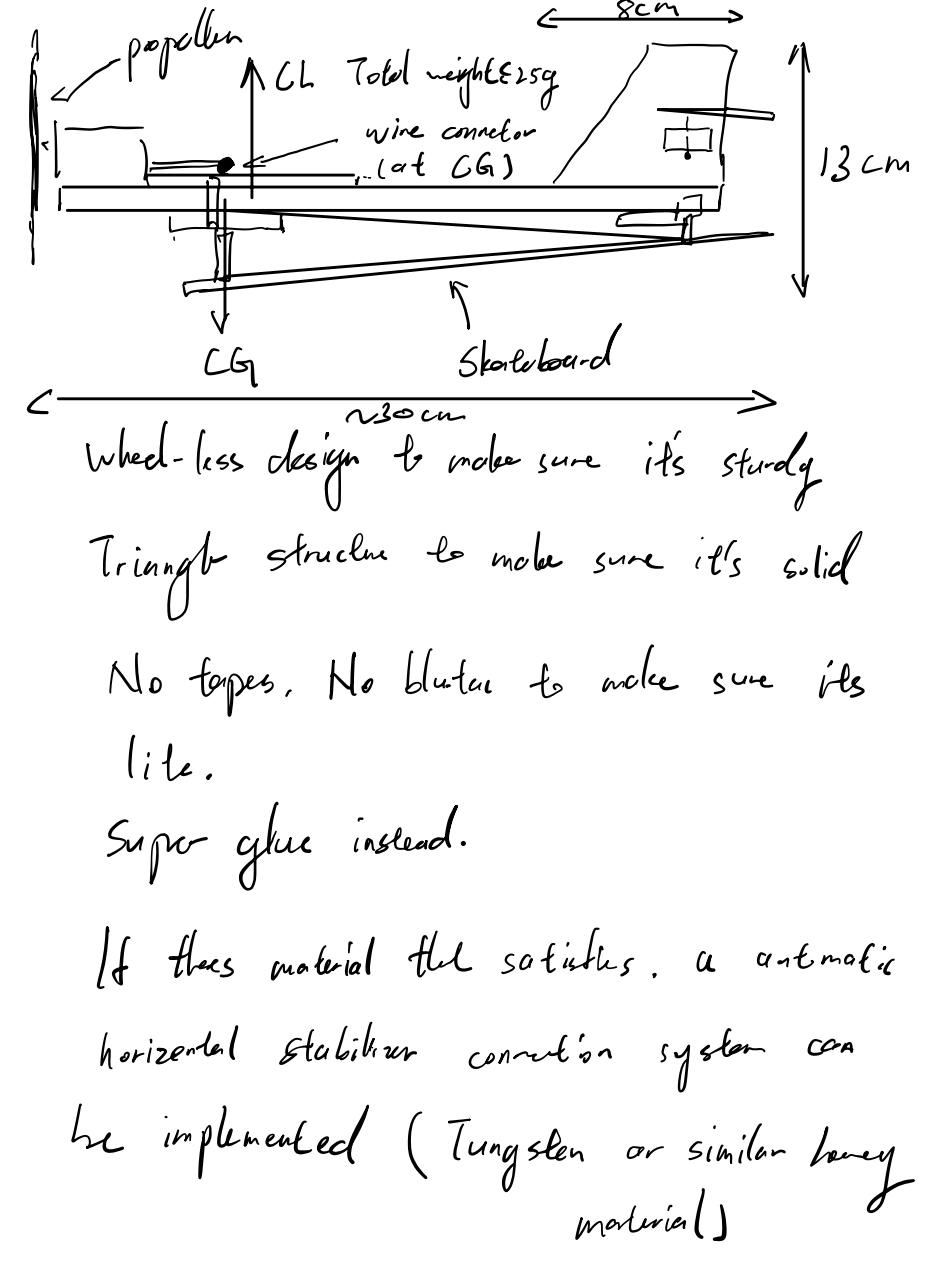
Figure 8: Advanced Design (Blueprint)
Redesigning the Undercarriage
The biggest change was replacing the front wheel with a ski-style support structure. The reason was that it cannot be completely removed as the propeller reaches below the fuselage while it is spinning. In other words, if the plane sat flat on the ground, the propeller would scrape and probably get destroyed before takeoff and after landing.
So I built a triangular balsa strut as shown in Figure 8, and mounted it under the fuselage near the nose. It lifted the nose just enough to prevent the propeller from touching the ground, and it reinforced the ground contact area. To avoid the same glue-joint failure as last time, I doubled up the balsa on every ground-contact surface of the strut and glued each layer across its full surface. It became much stronger than before.
I also increased the tail height a little. This was to ensure that the flight was in an orientation of a reasonable nose-up angle on the ground. This can also control the nose-up pitch angle by adjusting the height at the back.
Reinforcing the Motor Mount
For the motor, I switched from a single tape wrap to multiple overlapping wraps of electrical tape around the wing; the main one in the center went all the way around both the motor and the nose. The big difference is the contact area, which the tape now wraps the full circumference of the motor-fuselage joint, and this was also strengthened by more tape wraps.
Final Configuration
After all, all three problems mentioned before are solved as it became stronger enough, hopefully not to fall apart, and the AoA problem was solved. Figures 9 through 12 show the advanced design from different angles.
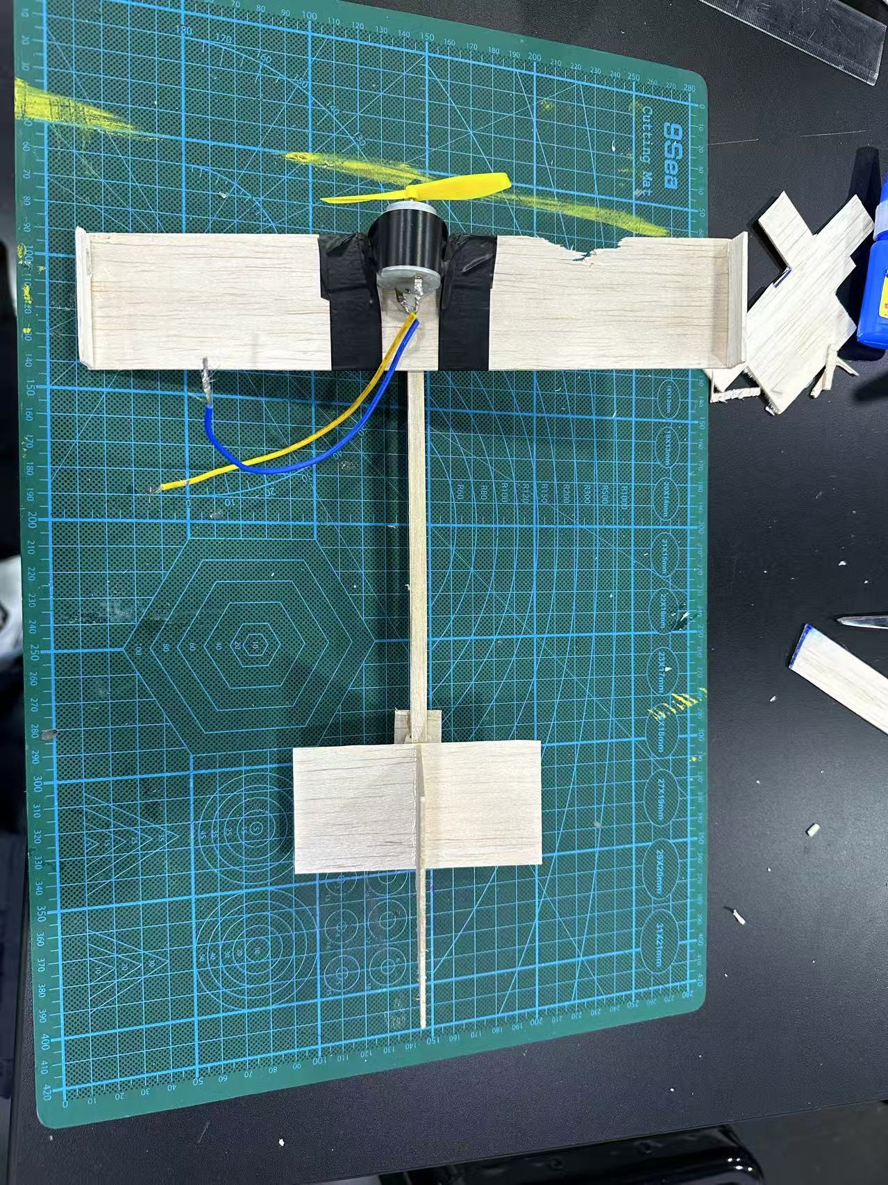
Figure 9: Advanced Design (Top View) 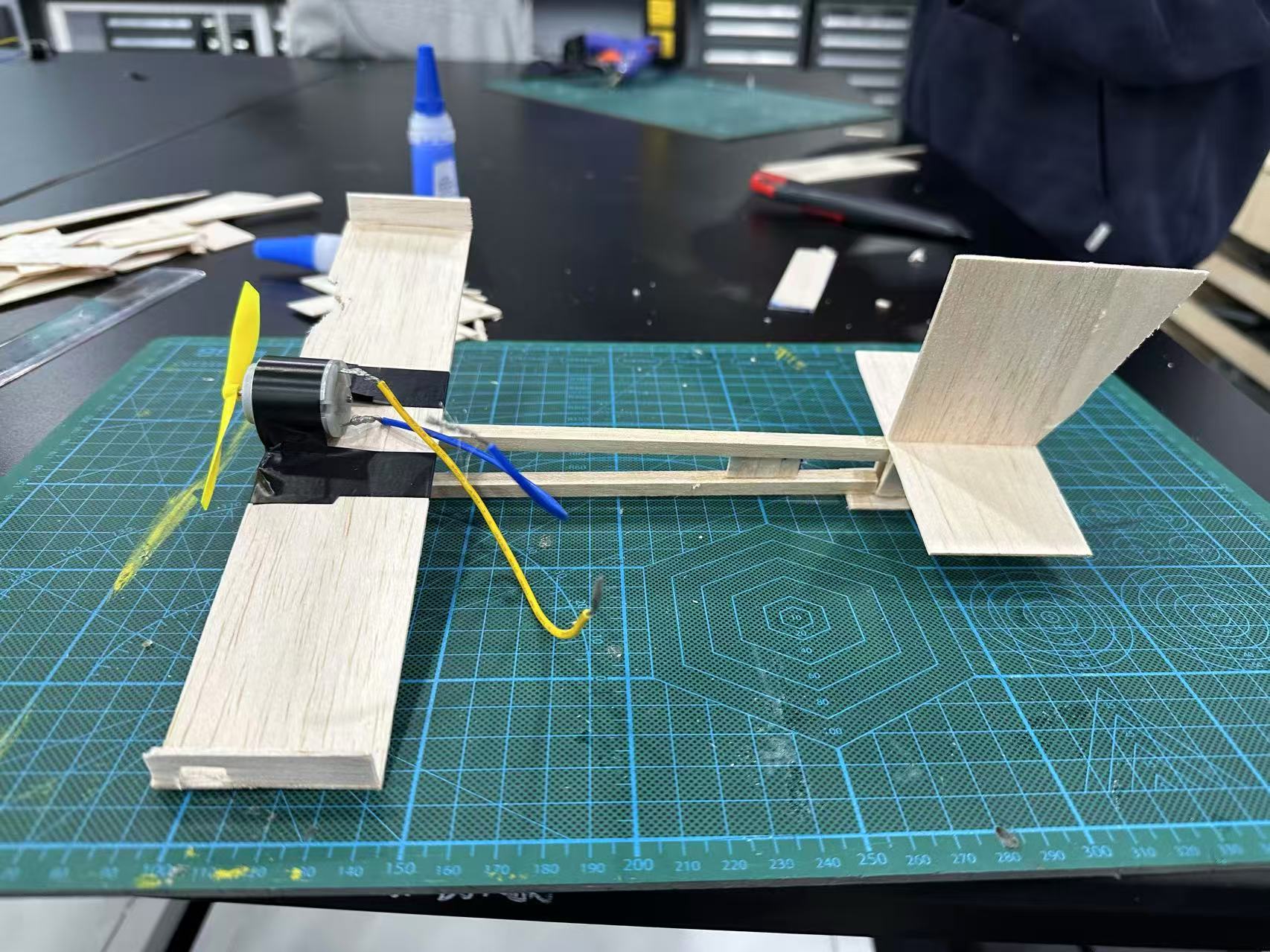
Figure 10: Advanced Design (Side View) 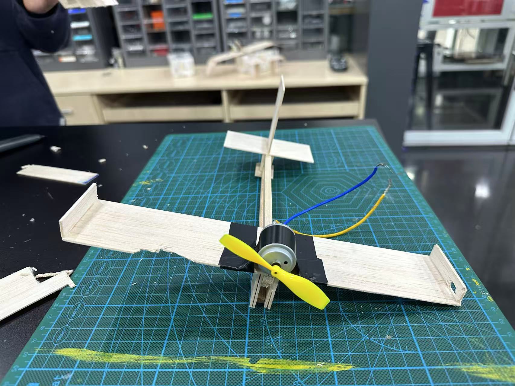
Figure 11: Advanced Design (Front View) 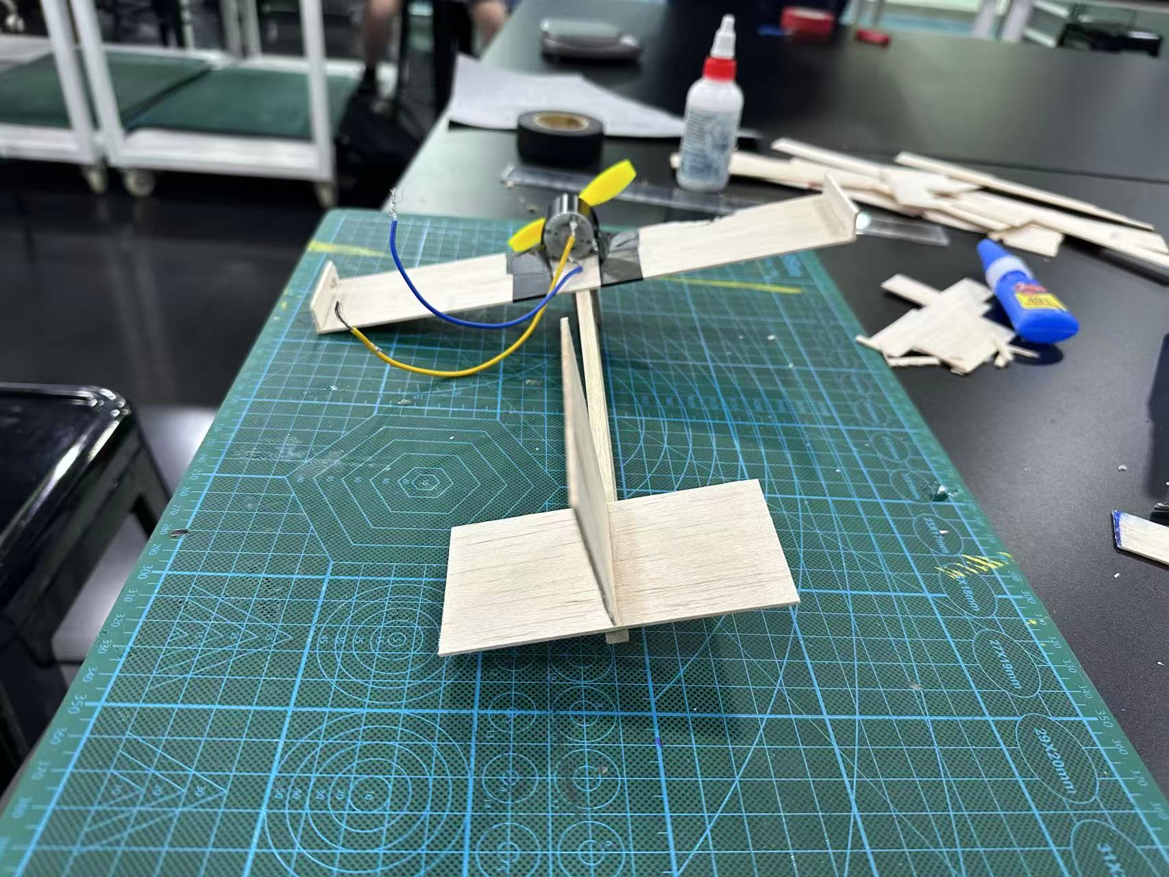
Figure 12: Advanced Design (Back View)
Trial: Advanced Design
The new plane was tethered to the central post and launched the same way as before. Figures 13 and 14 show it in the field, and Video 1 has the full flight.
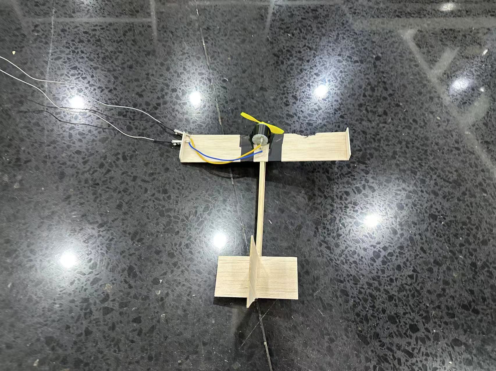
Figure 13: Advanced Design 1st Trial (Top View) 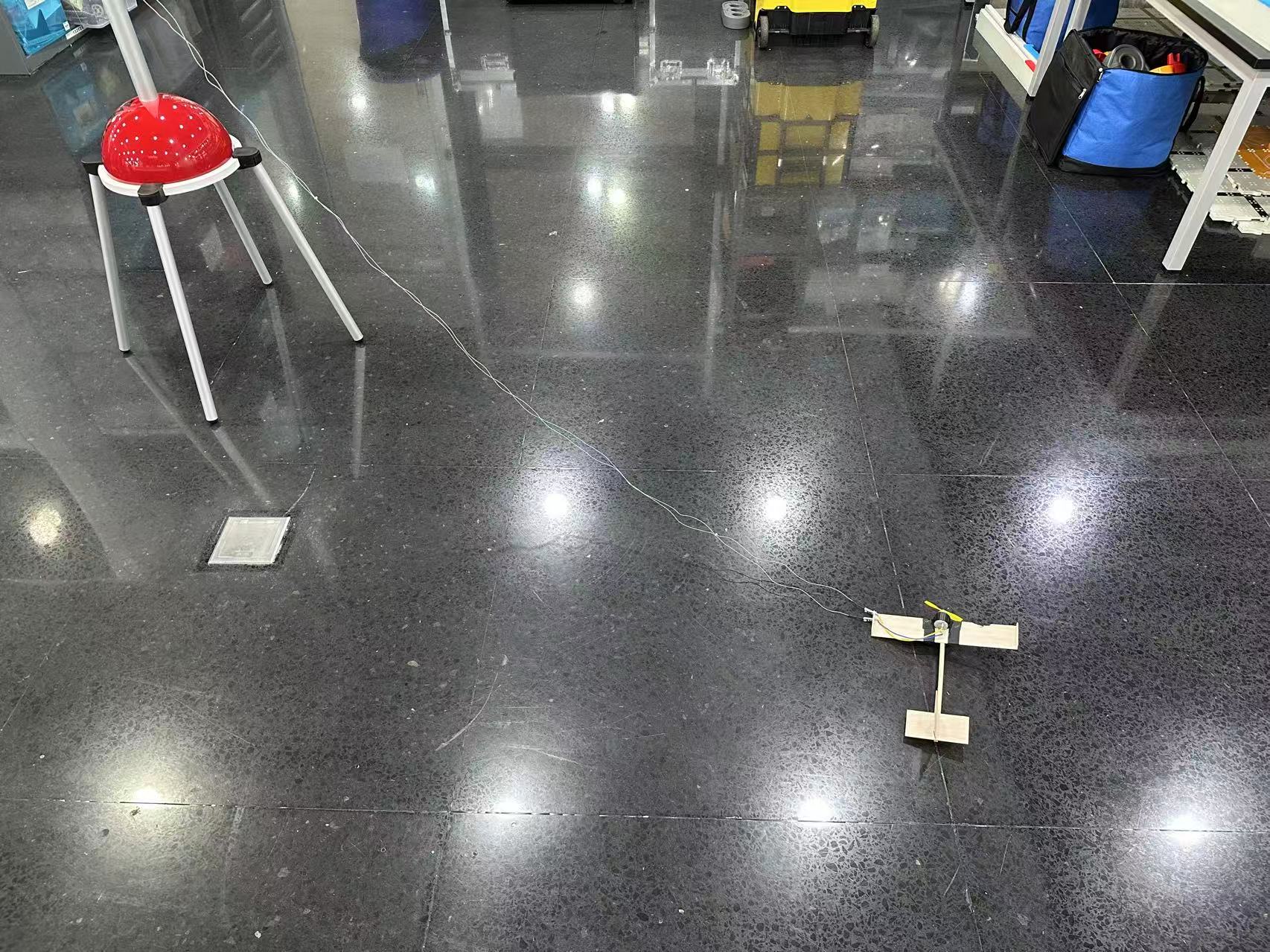
Figure 14: Advanced Design 1st Trial (Wide View)
Video 1: Advanced Design 1st Trial
Analysis
This time it actually worked as predicted. The plane accelerated along the ground, lifted off at a normal angle, and went into a stable circular path around the post. It held altitude, didn’t pitch up or down, and completed multiple full laps without anything breaking or coming loose.
One other thing I noticed during the flight: because the plane was flying in a circle, the tether was constantly pulling it inward. This is the centripetal force keeping it on the circular path. The vertical stabilizer also helped keep the nose pointed in the right direction throughout the turn, which kept the tether taut and stopped the plane from spiraling in or drifting outward.
In conclusion, the most important science of aerodynamics learned through this process would be the Angle of Attack related to the initial angle positioned to the fuselage. And this time, more engineering-related things are introduced since it has a motor, and higher strength was needed to complete the task as higher power was introduced.
References
Anderson, J. D. (2016). Introduction to Flight (8th ed.). McGraw-Hill Education.
Da Silva, A., & Kyriakides, S. (2007). Compressive response and failure of balsa wood. International Journal of Solids and Structures, 44(25–26), 8685–8717.
Raymer, D. P. (2018). Aircraft Design: A Conceptual Approach (6th ed.). AIAA Education Series.
Soden, P. D., & McLeish, R. D. (1976). Variables affecting the strength of balsa wood. Journal of Strain Analysis for Engineering Design, 11(4), 225–234.