Objectives
This project aims to engineer and construct a passively stable, unpowered fixed-wing aircraft optimized for maximum glide range and robust aerodynamic stability.
Primary Research Inquiries
-
What is the quantitative relationship between the Center of Gravity (CG) placement and the resulting longitudinal static stability and overall glide distance?
-
How does the wing aspect ratio (span relative to chord length) dictate aerodynamic efficiency concerning lift generation and induced drag?
-
In what capacity does the vertical stabilizer function to mitigate adverse yaw and maintain directional equilibrium?
-
How do angular modifications to the horizontal stabilizer dictate the pitching moment and govern longitudinal stability?
-
Which structural modifications can be implemented to minimize parasitic drag without inducing a proportional degradation in lift capacity?
Material Specifications
- Balsa Wood Sheet (1.5 mm x 75 mm x 915 mm) (1 unit)
- Balsa Wood Strut (5 mm x 5 mm x 50 mm) (1 unit)
- Thermoplastic Adhesive (Hot Glue) / Polyvinyl Acetate (Wood Glue)
- Precision Cutting Instrument
- Metric Ruler
- Protective Cutting Surface
- Elastomeric Bands (2 units)
Material Science: Orthotropic Properties of Balsa Wood
My evaluation of the balsa wood reveals highly orthotropic structural properties, meaning its mechanical strength varies significantly relative to its cellular grain orientation. Exerting a cutting force parallel to the longitudinal grain requires minimal shear stress, whereas perpendicular cuts demand substantially greater mechanical force.
During flight operations, the main wing is subjected to aerodynamic loading that generates significant bending moments at the distal wingtips. To optimize structural integrity, the principal grain direction must be oriented perpendicular to the fuselage. Aligning the grain parallel to the applied aerodynamic load is a structural flaw that significantly increases the likelihood of deformation or catastrophic wing failure. Orienting it correctly was a smart and essential design choice.
Fabrication Methodology
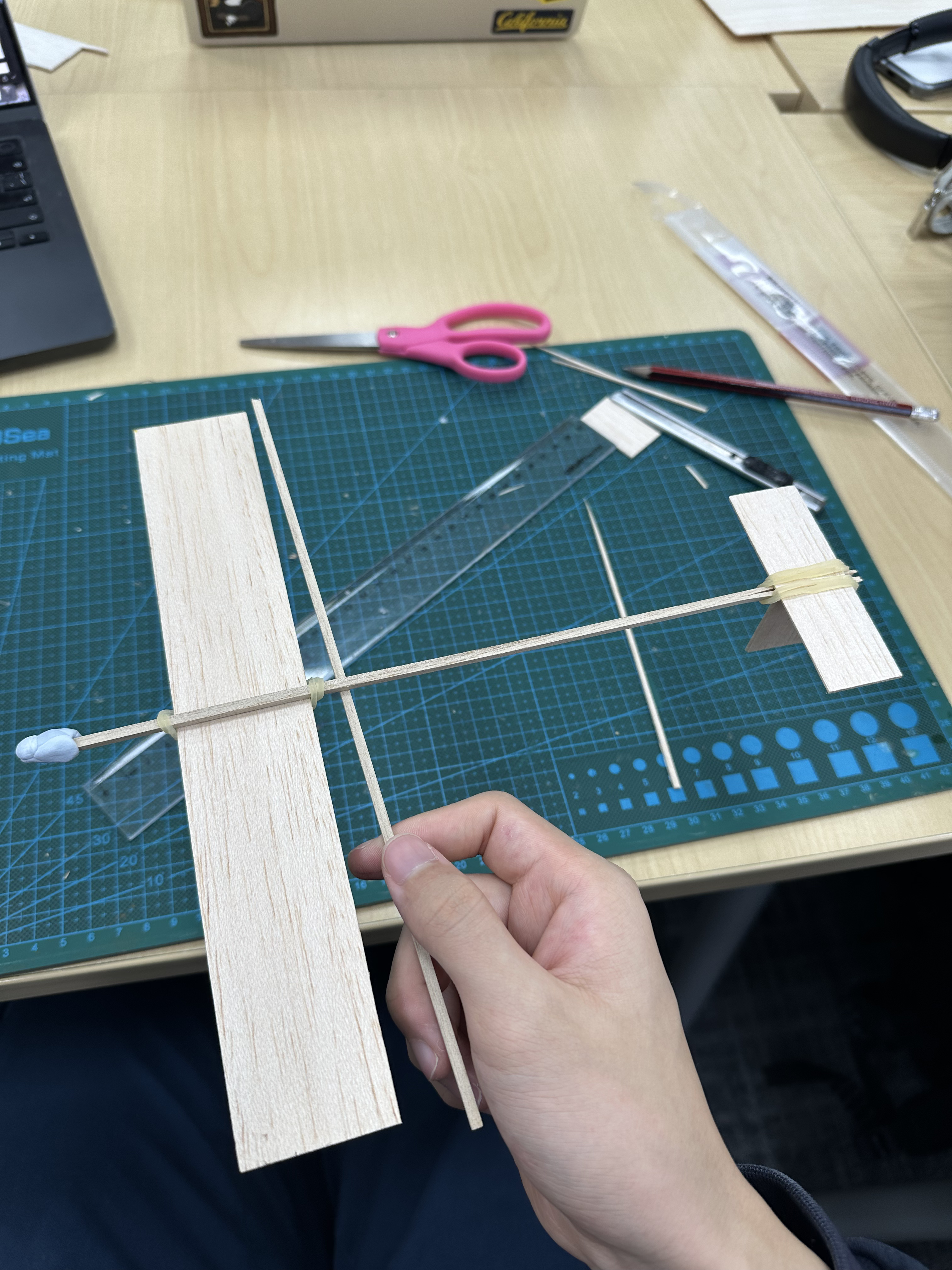
Three distinct planar surfaces were excised from the balsa sheet to form the aerodynamic lifting and stabilizing structures. The empennage was constructed by adhering the vertical stabilizer to the aft section of the fuselage strut.
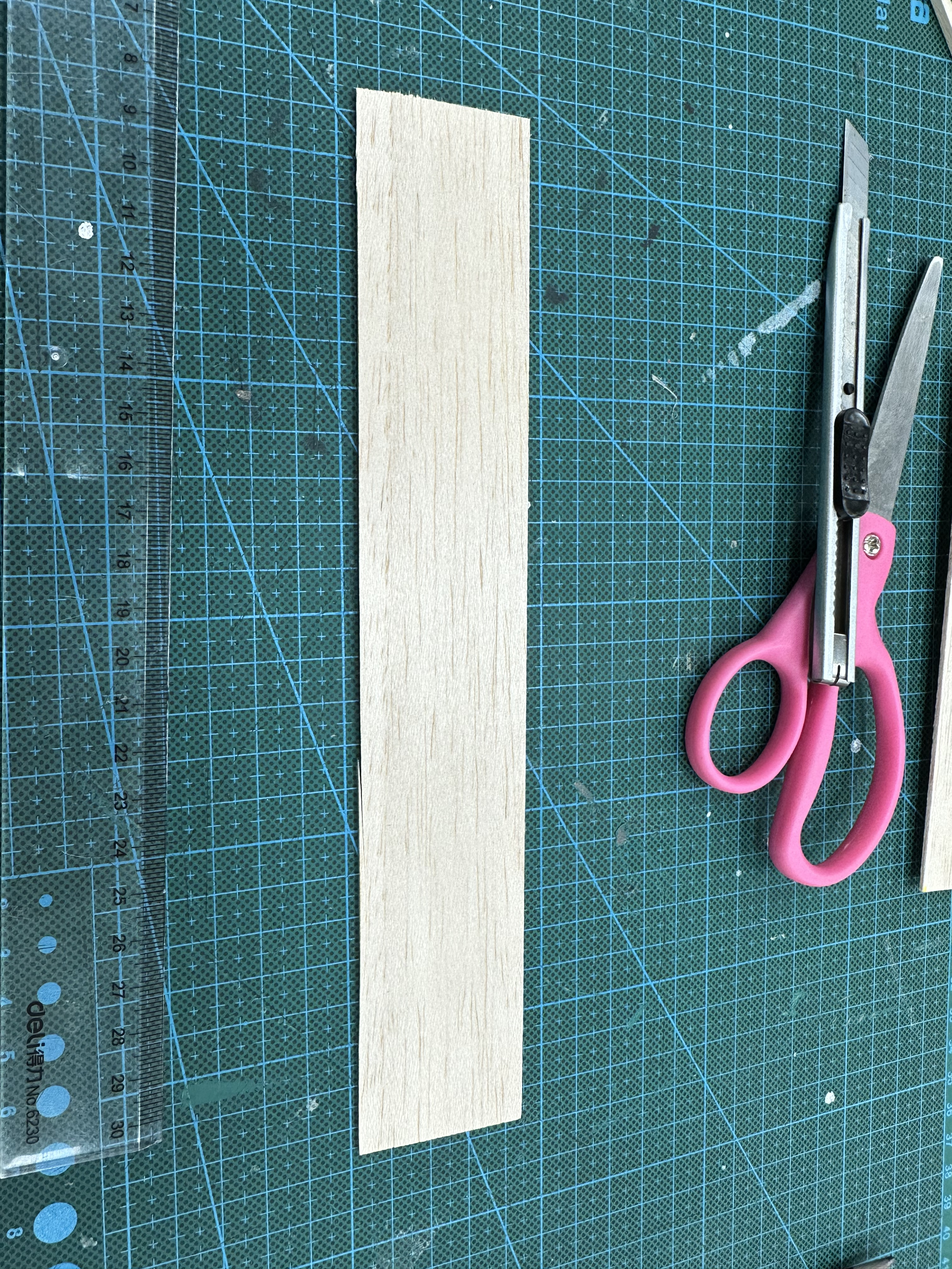
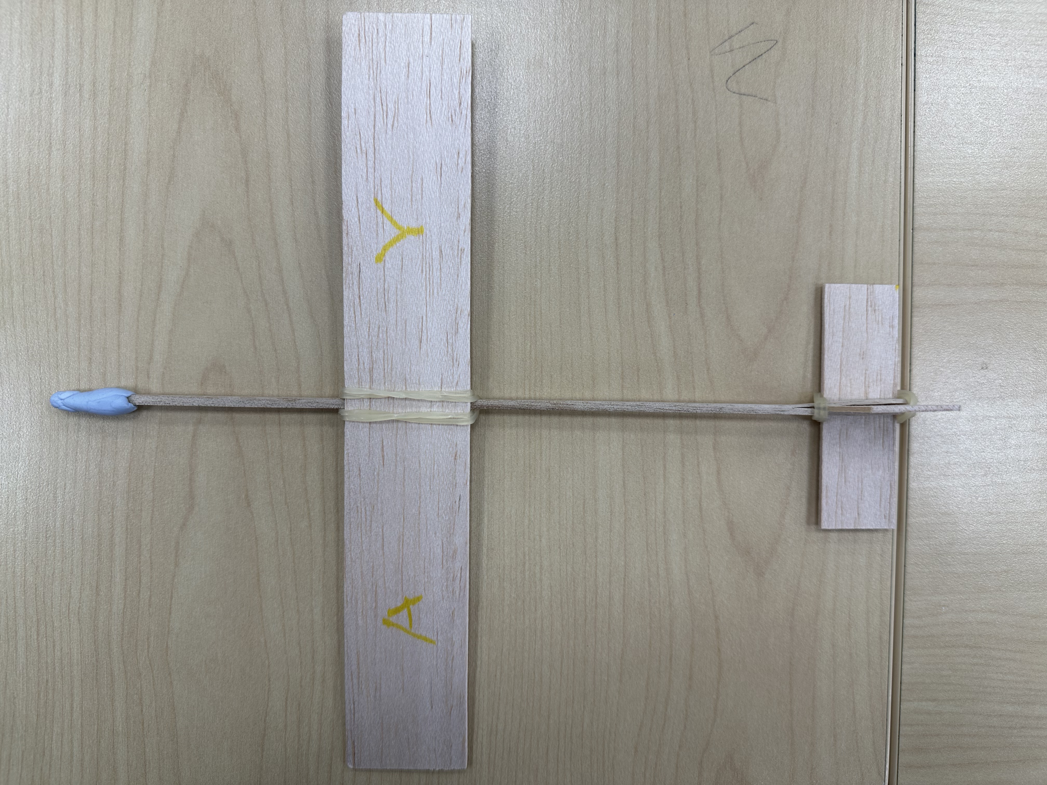
Figure 1: Raw Materials
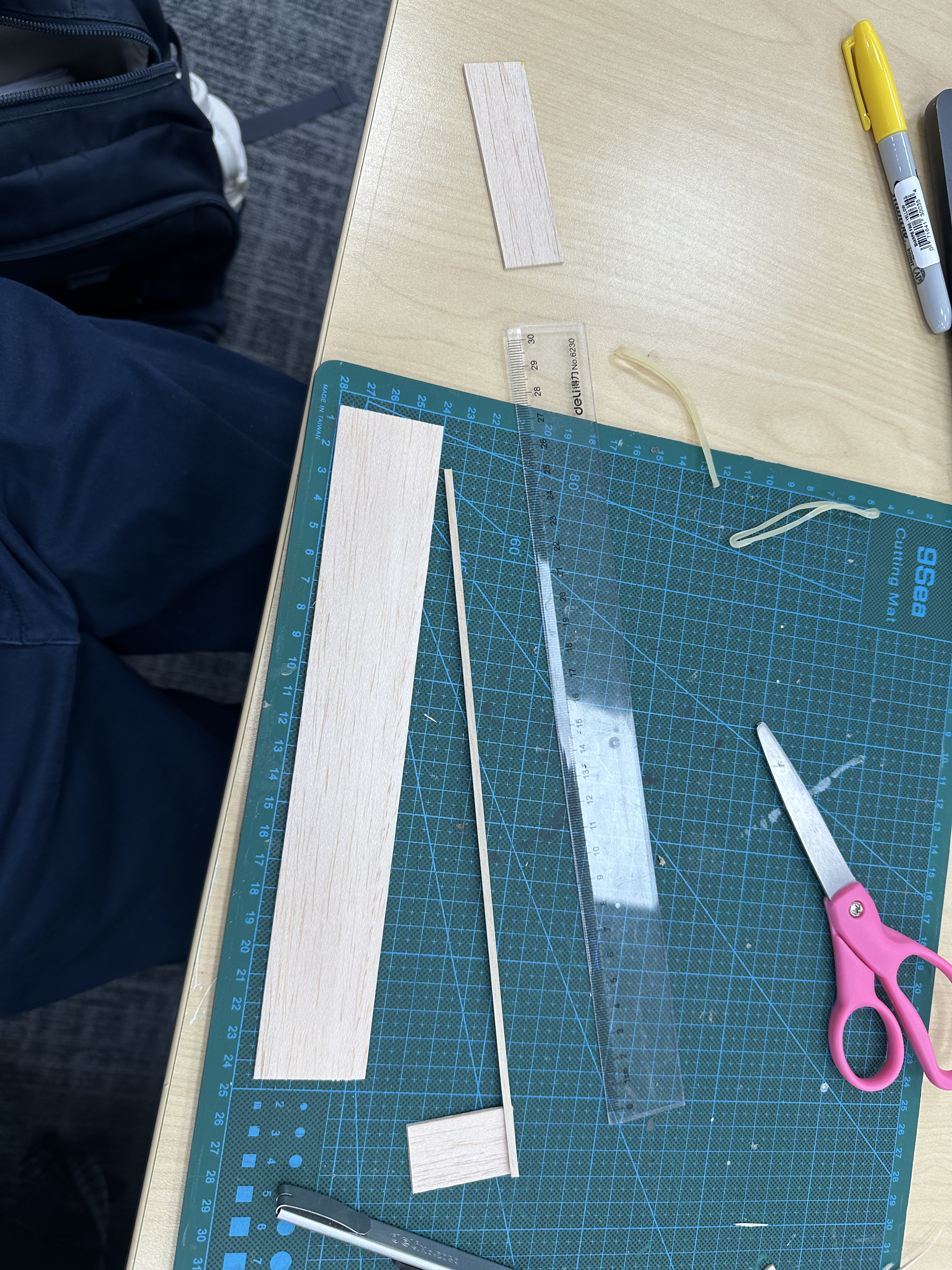
Figure 2: Vertical stabilizer installed
Elastomeric bands were utilized to temporarily secure the main wing and horizontal stabilizer to the fuselage. This non-permanent mounting solution is highly effective, as it permits iterative micrometric adjustments during the empirical testing phase.
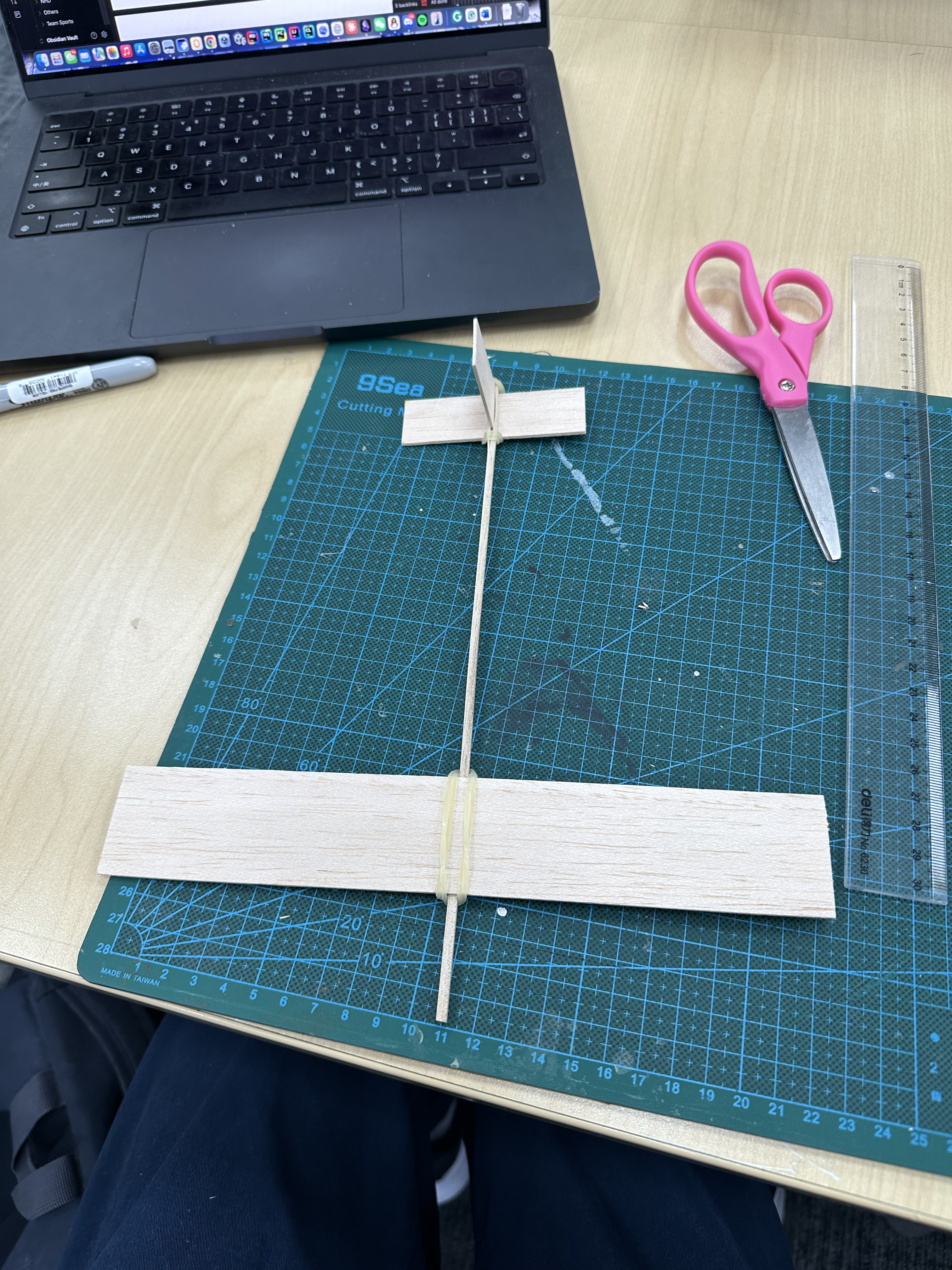
Figure 3: Bundled Wing and Stabilizer
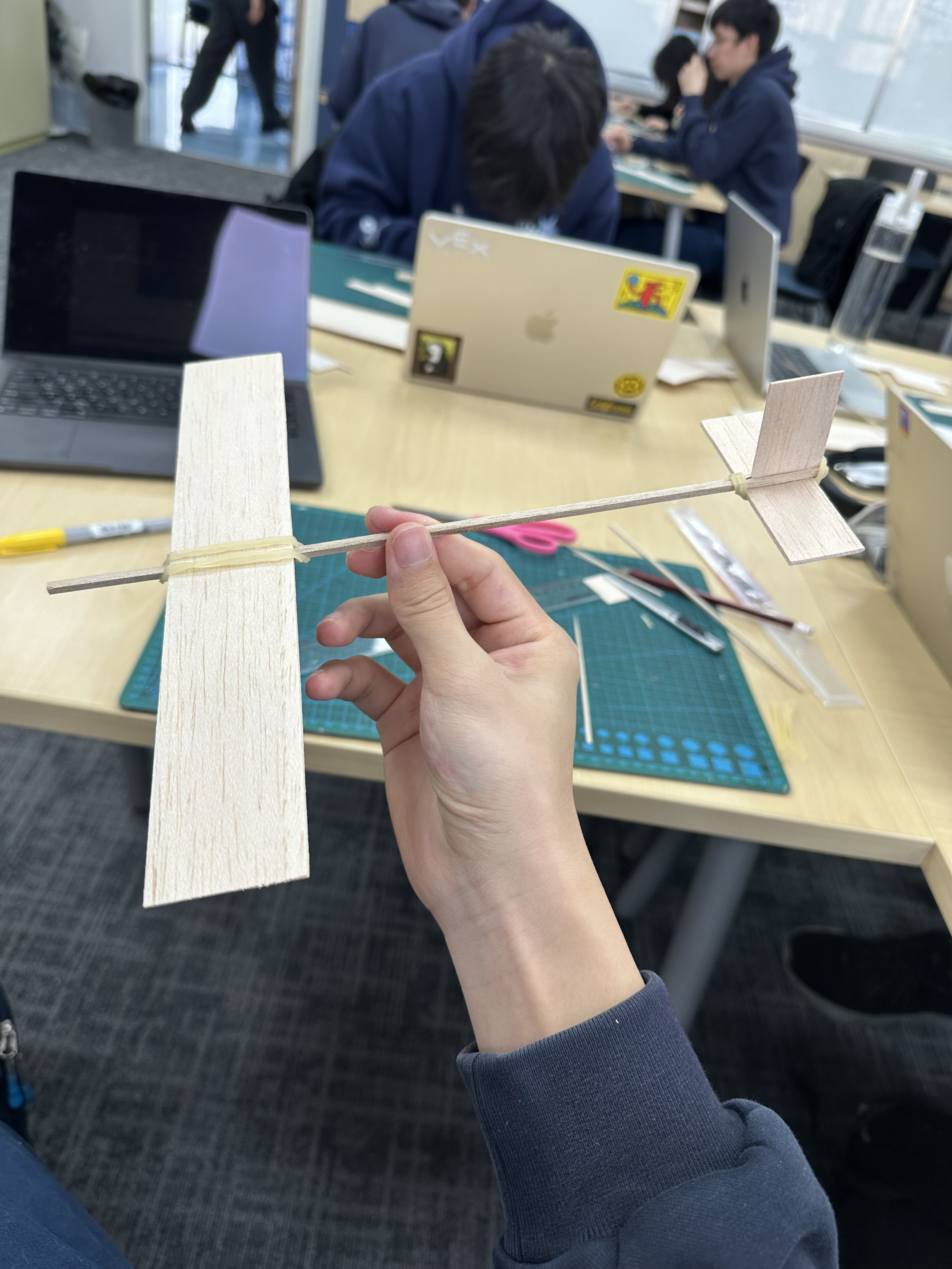
Figure 4: Final step before adding the forward ballast (Blu-Tack)
Prototype Specifications
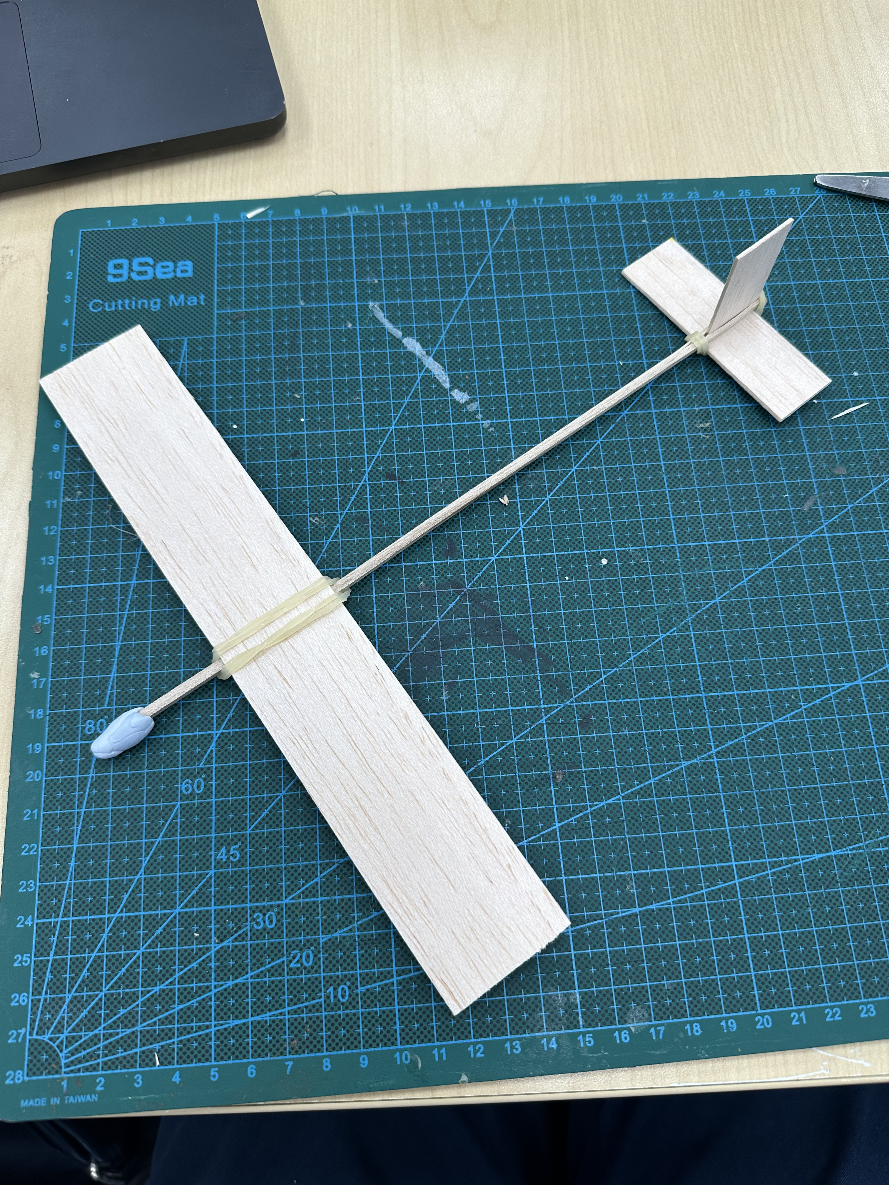
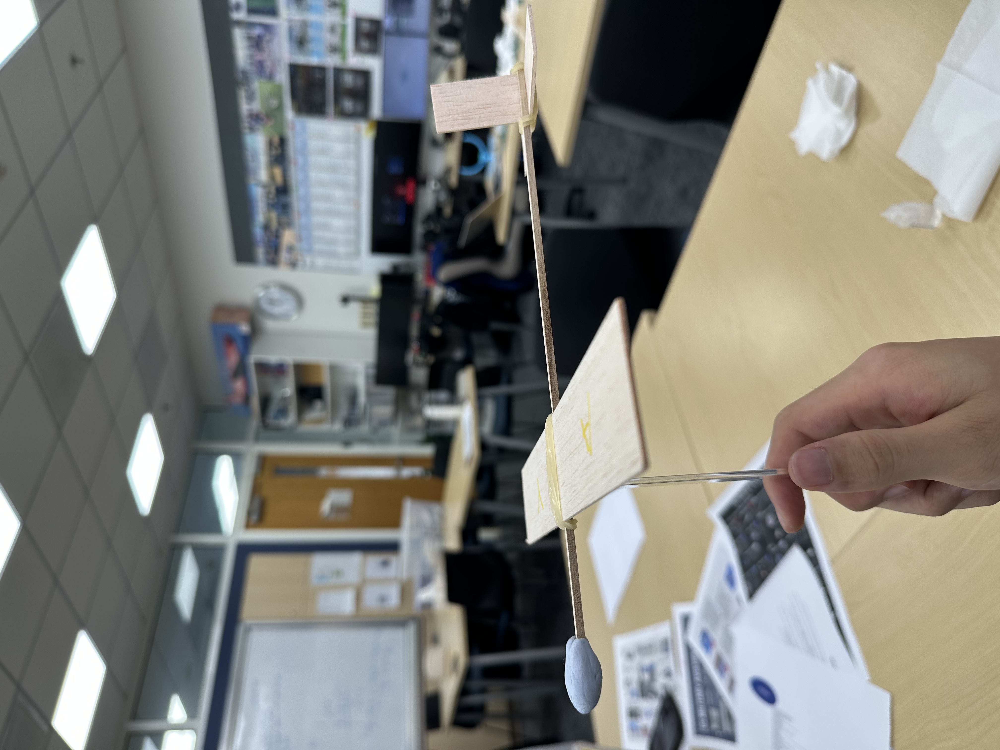
Figure 5: Final Product Side View
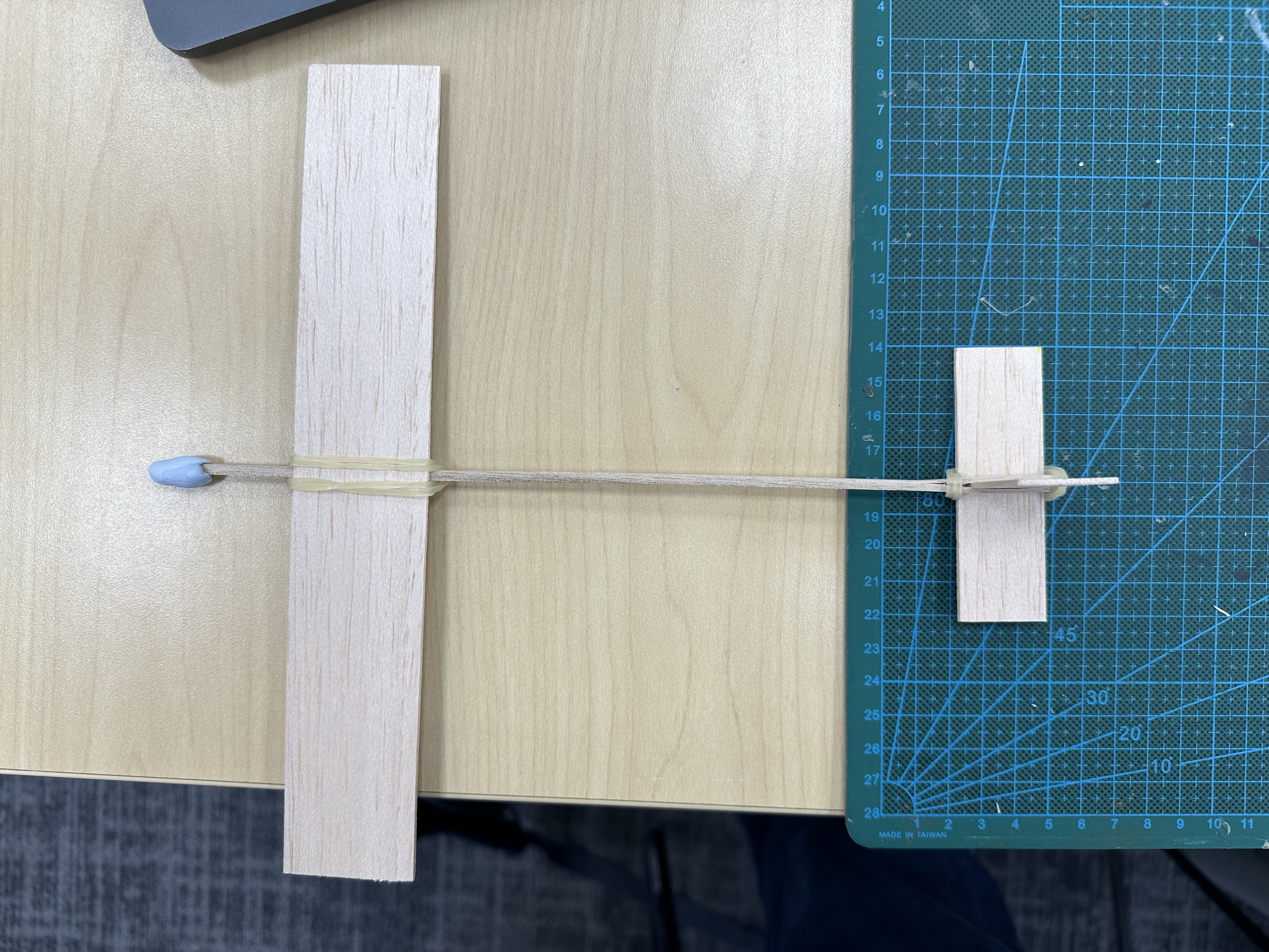
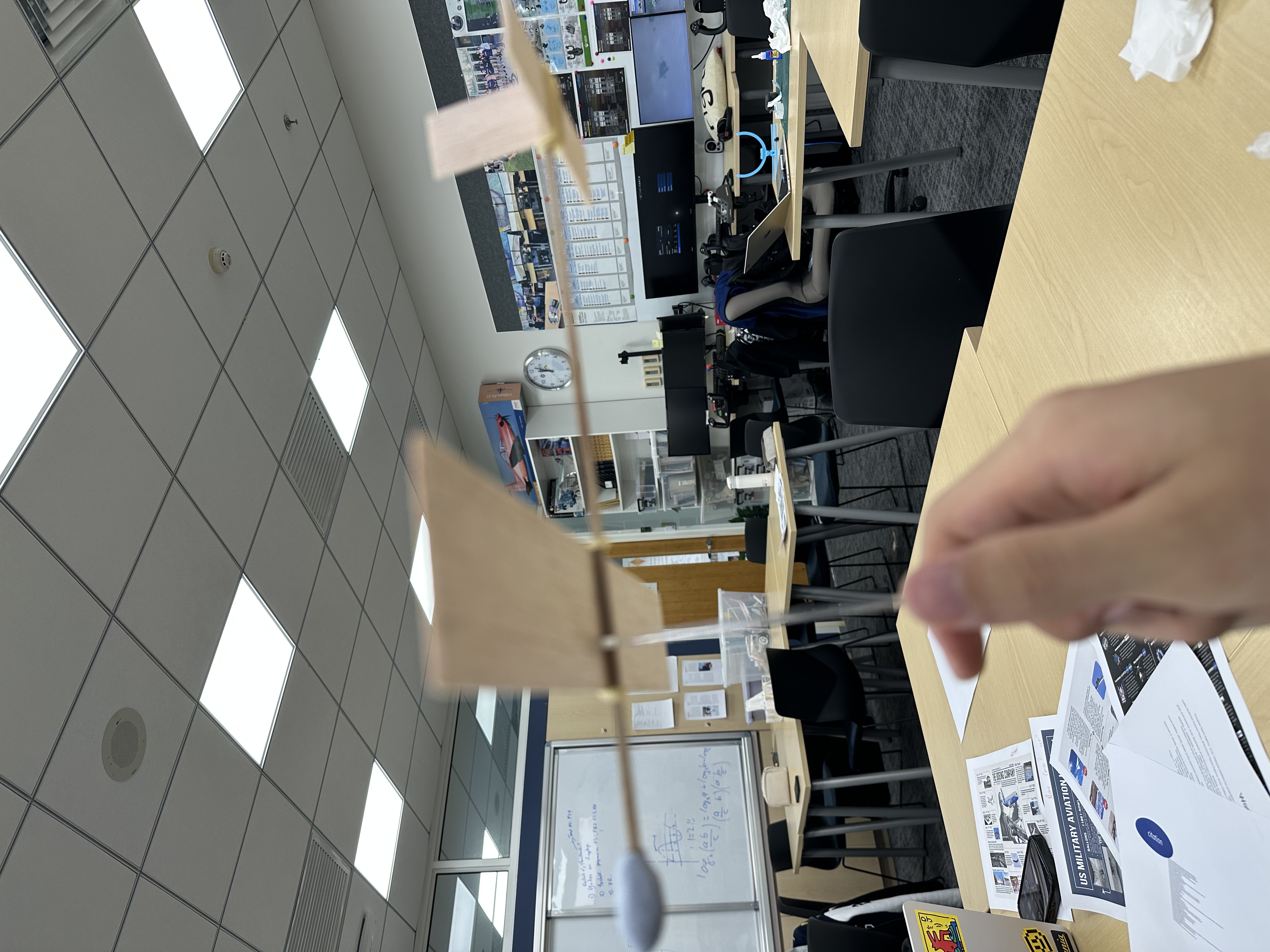
Figure 6: Final Product Top View
Dimensional Data
Wing: 20 cm x 4 cm
Horizontal Stabilizer: 8 cm x 2.5 cm
Vertical Stabilizer: 4 cm x 2.5 cm
Longitudinal Static Stability and Balancing
A fulcrum testing method was employed to ascertain the aircraft’s initial Center of Gravity (CG). The lateral axis demonstrated perfect equilibrium. However, the longitudinal CG was localized slightly aft of the main wing, which theoretically compromises stability.
.png)
Empirical Flight Testing and Aerodynamic Evaluation
Trial 1: Pitch Instability and Aerodynamic Stall
-
Hypothesis: The aircraft will experience immediate catastrophic altitude loss following a brief period of level flight due to a suboptimal static margin.
-
Observation: The aircraft experienced an immediate aerodynamic stall post-launch. The pitch attitude increased rapidly to approximately 45 degrees, leading to a critical loss of forward velocity, airflow separation over the airfoil, and a subsequent ballistic, backward descent.
Aerodynamic Analysis
To understand this failure mode, we must analyze the rotational forces (torques) acting upon the airframe, assuming point-mass physics for simplicity.
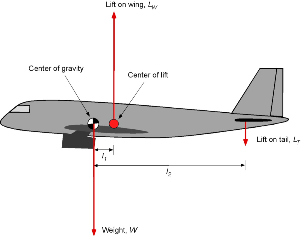
Center of Gravity (CG):
The spatial coordinate representing the mean position of the mass distribution. Gravity acts universally through this vector. It is an intrinsic property of the mass distribution and remains constant regardless of aerodynamic variables.
Center of Lift (Aerodynamic Center):
The dynamic point where the aggregate of all aerodynamic forces (lift and drag) acts. Unlike the CG, this point fluctuates depending on the angle of attack, freestream velocity, and specific airfoil geometry. It is strictly aerodynamic, not a mass property.
Pitching Moments:
-
Unstable Configuration: If the center of lift is positioned anterior (ahead) to the center of gravity, any pitch-up disturbance generates an aggravating nose-up pitching moment. This perfectly explains the stall observed in Trial 1.
-
Stable Configuration: If the center of lift is positioned posterior (behind) the center of gravity, it creates a restorative pitching moment.
For a conventionally configured aircraft to achieve longitudinal static stability, the CG must be positioned forward of the main wing’s center of lift. The tailplane (horizontal stabilizer) consequently generates a requisite downward aerodynamic force to trim the aircraft. If an external perturbation causes a pitch-up attitude, this configuration inherently produces a restorative nose-down moment, returning the aircraft to equilibrium.
Trial 2: Mass Redistribution and Center of Gravity Calibration
To rectify the extreme pitch instability, I translated the main wing aft along the fuselage and applied localized ballast (Blu-Tack) to the anterior nose section.
This structural modification yielded a significantly superior, flatter glide trajectory, definitively confirming the transition toward positive static stability. However, further optimization was required to maximize aerodynamic efficiency.
Trial 3: Optimization of the Static Margin
I executed precise micrometric adjustments to position the center of gravity at approximately 35% of the Mean Aerodynamic Chord (MAC), measured from the leading edge of the main wing. This optimal static margin ensured that the center of mass and the center of lift were theoretically aligned to produce a continuous, highly stable glide path.
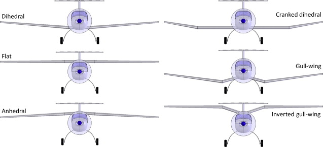
Lateral Stability and the Dihedral Effect
To enhance the aircraft’s lateral static stability, a dihedral angle was incorporated into the main wing structure. In my professional evaluation, this is one of the most critical modifications for unpowered gliders, as they lack active control surfaces to correct roll disturbances.
When an atmospheric disturbance induces an uncommanded roll, a wing featuring a dihedral angle automatically generates a restorative rolling moment.
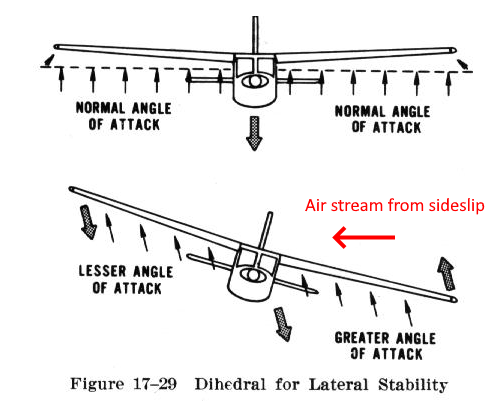
Sideslip Mechanics and Dihedral Recovery:
Should the aircraft roll to the starboard (right) side, it begins to side-slip in that direction.
- The right wing drops lower.
- The left wing rises higher.
- The relative freestream airflow approaches the airframe asymmetrically from the side.
Due to the dihedral geometry, the lower wing intercepts the relative airflow at a superior effective angle of attack compared to the elevated wing. This discrepancy generates a proportional, asymmetric lift distribution; the lower wing produces significantly more lift, effectively rolling the aircraft back to a level attitude. Ultimately, the primary aerodynamic function of the dihedral angle is to ensure a natural, self-correcting roll recovery tendency during a sideslip event.
Advanced Design
Main Focus
- high-mounted main wing
- moderate dihedral / polyhedral
- conventional tail instead of canard or flying wing
- slender fuselage
- forward ballast-ready nose
- slightly undercambered or flat-bottom wing
- carefully chosen tail volume for automatic stability
This is not the most “flashy” design, but it is the best serious design for stable, long glide with your limited material.
Configuration
- Type: Hand-launch balsa glider
- Goal: Stable, farthest glide
- Wing position: High wing
- Wing planform: Center panel + two tip panels (polyhedral)
- Tail: Conventional tail
- Fuselage length: 26.7 cm stick used nearly as full fuselage core
- Target glide style: Slightly descending, smooth, no stall, very mild left or right turn allowed
Dimensions
Main Wing
Wing total span: 36 cm
big enough for a good lift
not so large that it becomes floppy or twisty
Wing chord
6.0 cm center chord
- Center panel: 14 cm span × 6.0 cm chord
- Left tip panel: 11 cm span × 6.0 cm root chord tapering to 4.2 cm tip chord
- Right tip panel: same as left
This gives a good aspect ratio, better lateral stability, and lower tip drag than a pure rectangular wing.
Wing area estimate
- center panel area = 14 × 6.0 = 84 cm²
- each tip panel area ≈ 11 × (5.2 + 4.2)/2 = 51.7 cm²
- total wing area ≈ 187 cm²
Horizontal Stabilizer
Span: 14.0 cm
Chord
- 3.2 cm root
- 2.6 cm tip
Area
About 40–42 cm²
Vertical Stabilizer
Height above fuselage: 5.0 cm
Root length along fuselage: 4.5 cm
Tip chord: 1.5 cm
Area roughly 13–15 cm²
Fuselage
26.7 cm wooden stick as the main fuselage boom
Fuselage layout along the stick
Measured from the nose
- 0.0–2.5 cm: nose/ballast zone
- 7.5–8.5 cm: wing mount center
- 22.8–23.5 cm: horizontal tail leading edge
- 22.8–23.5 cm: vertical tail root front
Material Allocation
500 cm² total sheet area
Main wing
- 187 cm²
Horizontal stabilizer - about 42 cm²
Vertical stabilizer - about 15 cm²
Others - about 20–30 cm²
Total - Roughly 264–275 cm²
Reinforcement pieces
- 2 wing joint gussets: 2.5 cm × 1.5 cm triangles or diamonds
- 1 center wing doubler: 5.0 cm × 2.0 cm
- 2 tail mount tabs: 1.5 cm × 0.8 cm
- several trim tabs: 0.8 cm × 0.4 cm small strips
Airfoil
Since the balsa sheet is a thin sheet of wood, it is not able to build a ribbed airfoil.
Dihedral
Use polyhedral
Center panel stays nearly flat
Each tip panel rises at about 12–14 degrees relative to the center panel
When the center panel lies flat on the table, each tip should rise about 2.3–2.7 cm
Incidence Angles
Main wing
- 2.0 degrees relative to the fuselage stick
Horizontal Stabilizer
- -0.5 degrees relative to the fuselage stick
Decalage
So the wing-to-tail incidence difference is about 2.0 to 2.5 degrees
Center of Gravity
Set the CG at 40% of the main wing chord measured from the leading edge at the center panel.
For 6.0 cm chord, 40% = 2.4 cm behind leading edge
If the plane stalls
- CG is too far back
If it dives hard
- CG is too far forward
Exact Placement on Fuselage
Using the 26.7 cm stick, measure from the nose
Wing
- wing leading edge at fuselage centerline: 7.2 cm from nose
- The wing quarter-chord is then about 8.7 cm from the nose
Horizontal Sabilizer
- tail leading edge: 22.8 cm from nose
- tail quarter-chord around 23.6 cm from the nose
Vertical Stabilizer
Place directly above the rear fuselage, front of the fin begins around 22.8 cm from the nose, aligned with the horizontal tail leading edge