Basic Aerospace with Paper Airplanes
This is an assignment on timeline in aerospace for the AL Aerospace Engineering course at Concordia International School conducted by Dr. Peter Tong (aka D.T). In this article, I documented the full process of building three different paper airplane designs, testing them under controlled conditions, analyzing the results, and connecting my observations to basic aerodynamic theory.
Objective
Compare flight performance across designs and identify which design variables most affect distance, stability, and trajectory.
Design
Controlled variables
- Same paper size
- Folding precision status
- Test location, environment (wind, pressure, temp, etc.)
- Launch height & force & Method (by hand)
Independent variables
- Plane design
Dependent variables
- Distance (cm)
- Drift direction (PYR)
Background: The Four Forces of Flight
Before building and testing, it is important to understand the four fundamental forces acting on any aircraft in flight: Lift, Weight, Thrust, and Drag (Anderson, 2016). For a paper airplane, thrust is provided entirely by the initial throw, after which the plane becomes a glider which means that lift must be sustained by the wing shape and forward momentum alone, while drag and gravity constantly work to slow and pull the plane down (see Fig 1). The balance point between these forces, particularly the relationship between the center of gravity (CG) and the center of lift (CL) determines whether the plane flies stably or pitches uncontrollably (Tennekes, 2009).
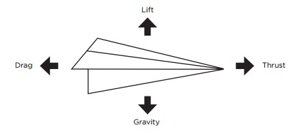
Fig 1: Diagram of the four forces acting on a paper airplane in flight (Lift, Weight, Thrust, Drag).
Do
I followed every single step in the instructions and had no issue. However, I paid close attention to several details during the folding process. I used a flat desk surface and a ruler edge to make each crease as sharp and symmetric as possible, since even micro level fold deviations can shift the center of gravity and create asymmetric drag profiles (Blackburn, 2006). For each plane, I ensured the paper was oriented consistently and that all folds were aligned with the printed guide lines before committing to a crease. The controlled variables (same paper stock, same indoor environment with no wind, same launch height of approximately 1.8 m, and a consistent overhand throw) were maintained throughout all test flights.
#3 Plane
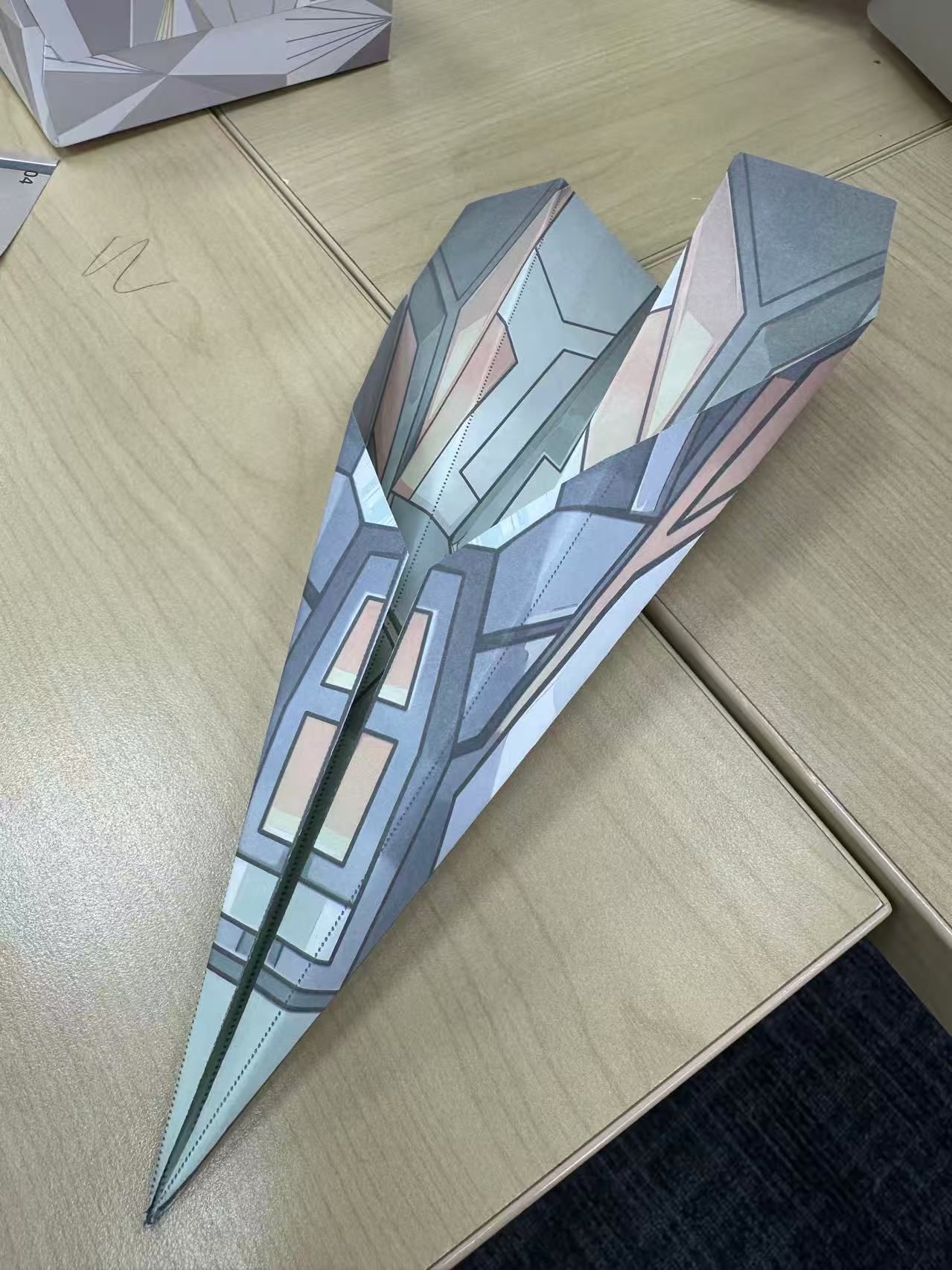 Fig 2: Completed Plane #3.
The folding process is very simple: I just fold the top 2 corners to the center, make sure the top edges touch the middle line, then do that again. Then fold the middle line and finally fold the flat surface. It flies well since there’s no significant frontal area creating air resistance. As I throw it stronger, it flies farther. It also depends on the angle I throw, an angle from 0 to 30 is optimal. A larger angle would cause it to change its angle too early and dive straight towards the floor.
This behavior is consistent with the concept of angle of attack (AoA): when AoA exceeds a critical threshold (about 15 to 20° for most flat-plate airfoils), the airflow separates from the upper surface of the wing, causing a dramatic loss of lift known as a stall (Anderson, 2016). For a paper dart, the optimal launch angle keeps AoA within a range where lift-to-drag ratio is maximized.
#4 Plane
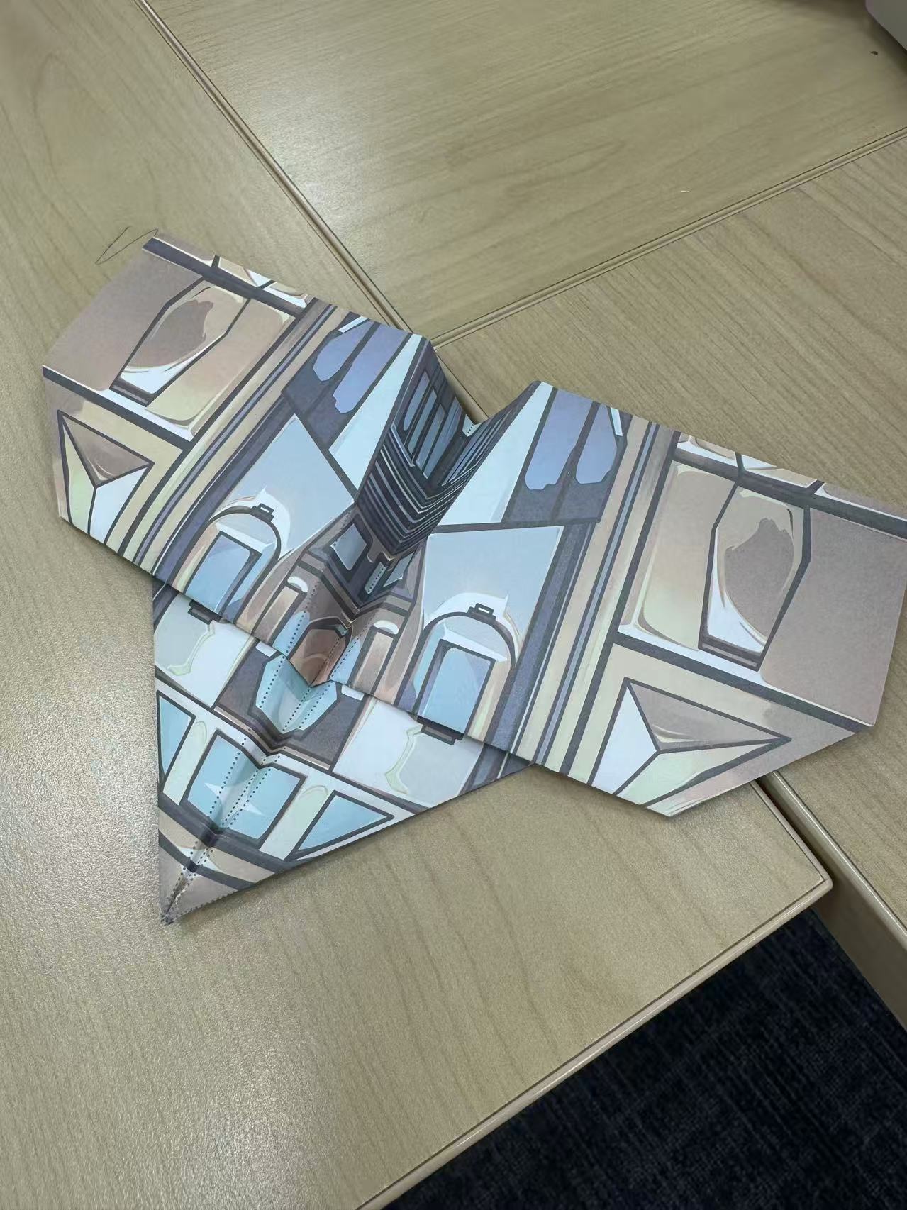 Fig 3: Completed Plane #4.
This design performed very poorly, as it always yawed erratically and did not fly far. It was because there was a huge frontal obstacle that blocked the air on the plane. In specific, the blunt nose of Plane #4 creates a large frontal cross-section, which tremendously increases drag, the resistance caused by the shape of the aircraft pushing through the air (NASA, 2021). This drag overpowers the initial thrust almost immediately after the throw and causes rapid deceleration and loss of control.
#6 Plane
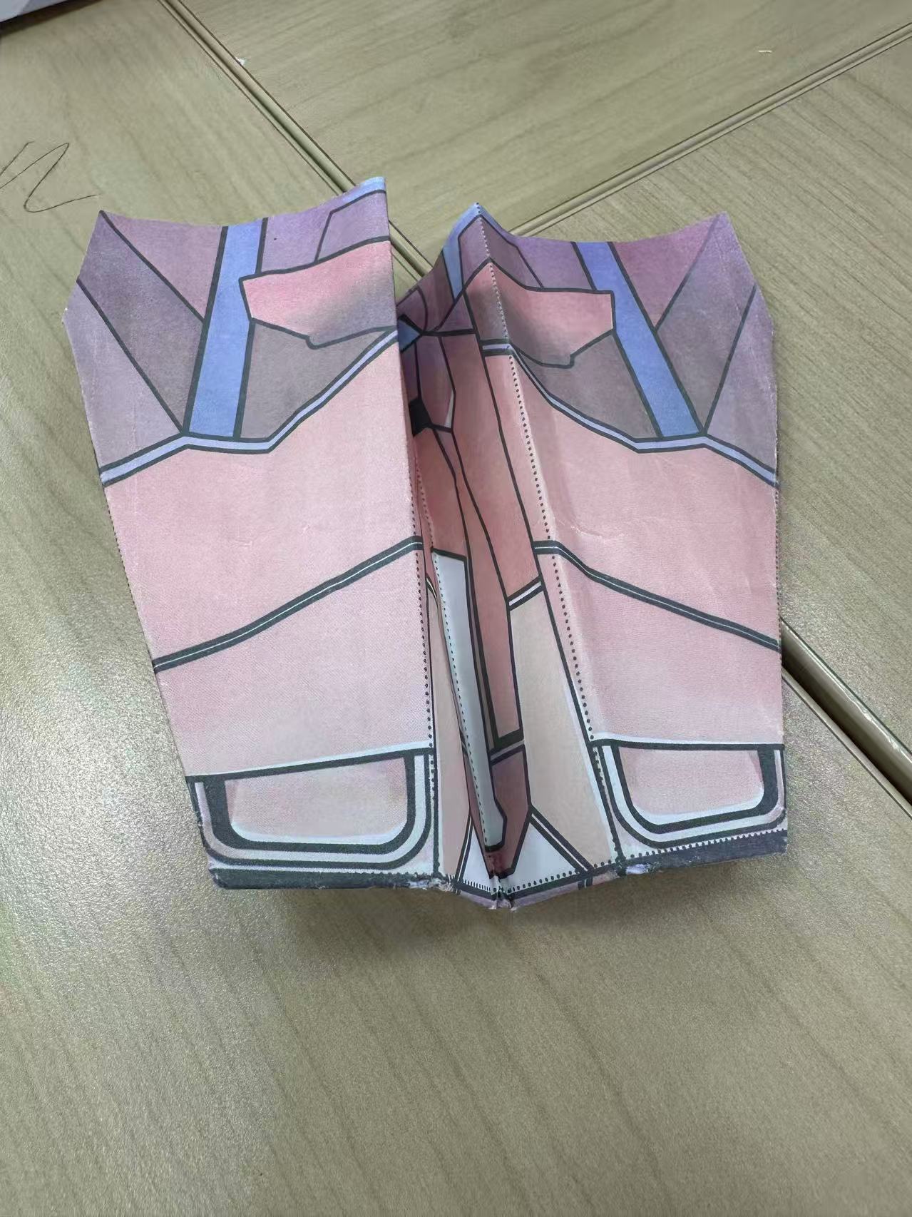 Fig 4: Completed Plane #6.
This plane works a lot better than #4, but still not the most optimal one. It usually flies flat at first, but then pitches up and hits the ceiling.
According to aerodynamic principles, it might be because the center of gravity is located toward the rear of the aircraft. There’s no significant up-elevator visible on this plane, so that is the most likely reason. When the CG sits behind the CL, the nose tends to pitch upward, creating an unstable flight condition. This is a well-known principle in aircraft design: a forward CG promotes stability, while a rearward CG promotes instability (Tennekes, 2009).
It might also be because someone made this paper wrinkly, so it flies badly. Wrinkled paper creates uneven surface texture that disrupts the thin boundary layer over the wing, introducing turbulent airflow patches that reduce lift consistency (Blackburn, 2006).
Comparison
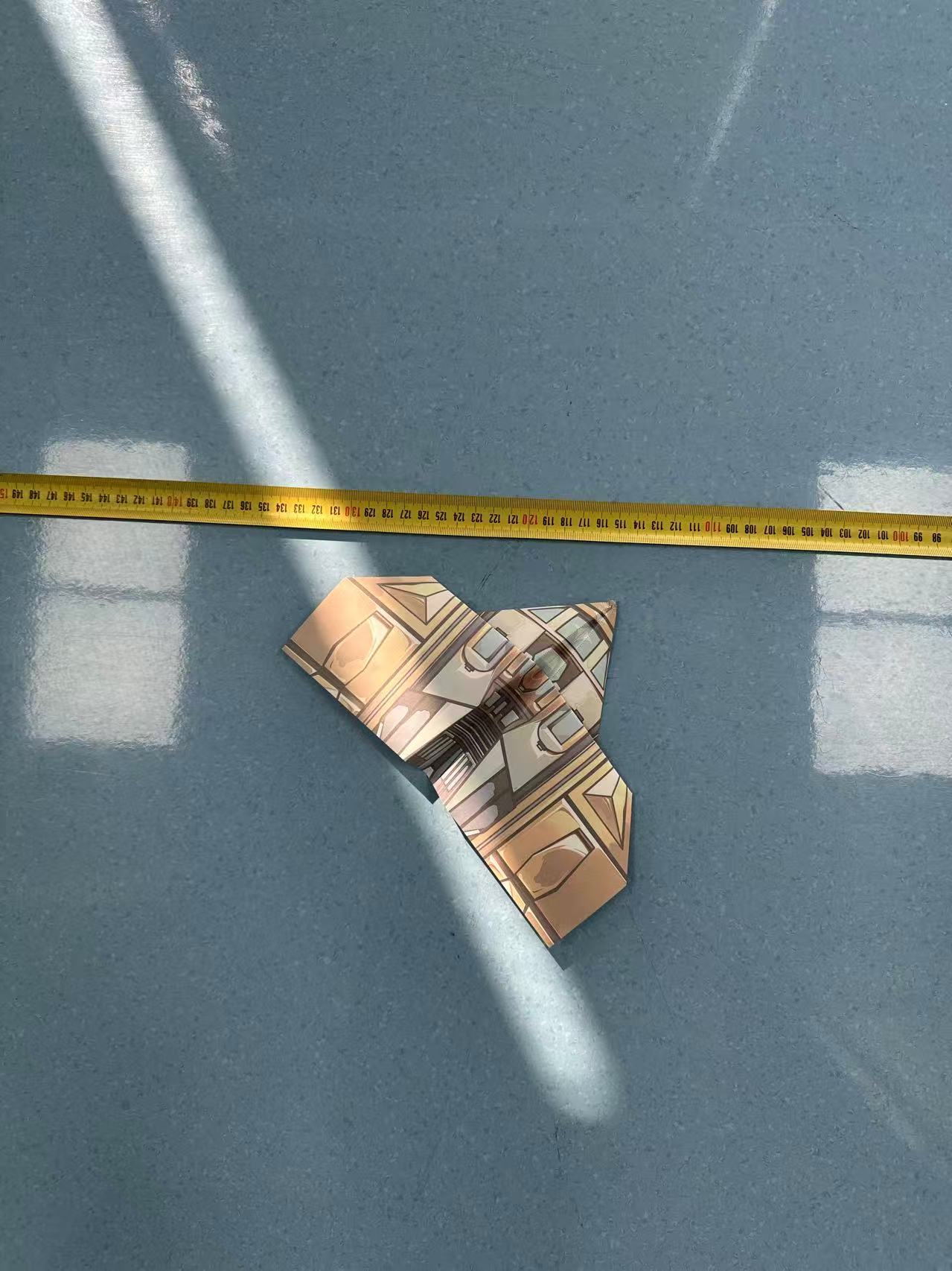
Fig 5: Side-by-side comparison of all three plane designs before test flight 1.
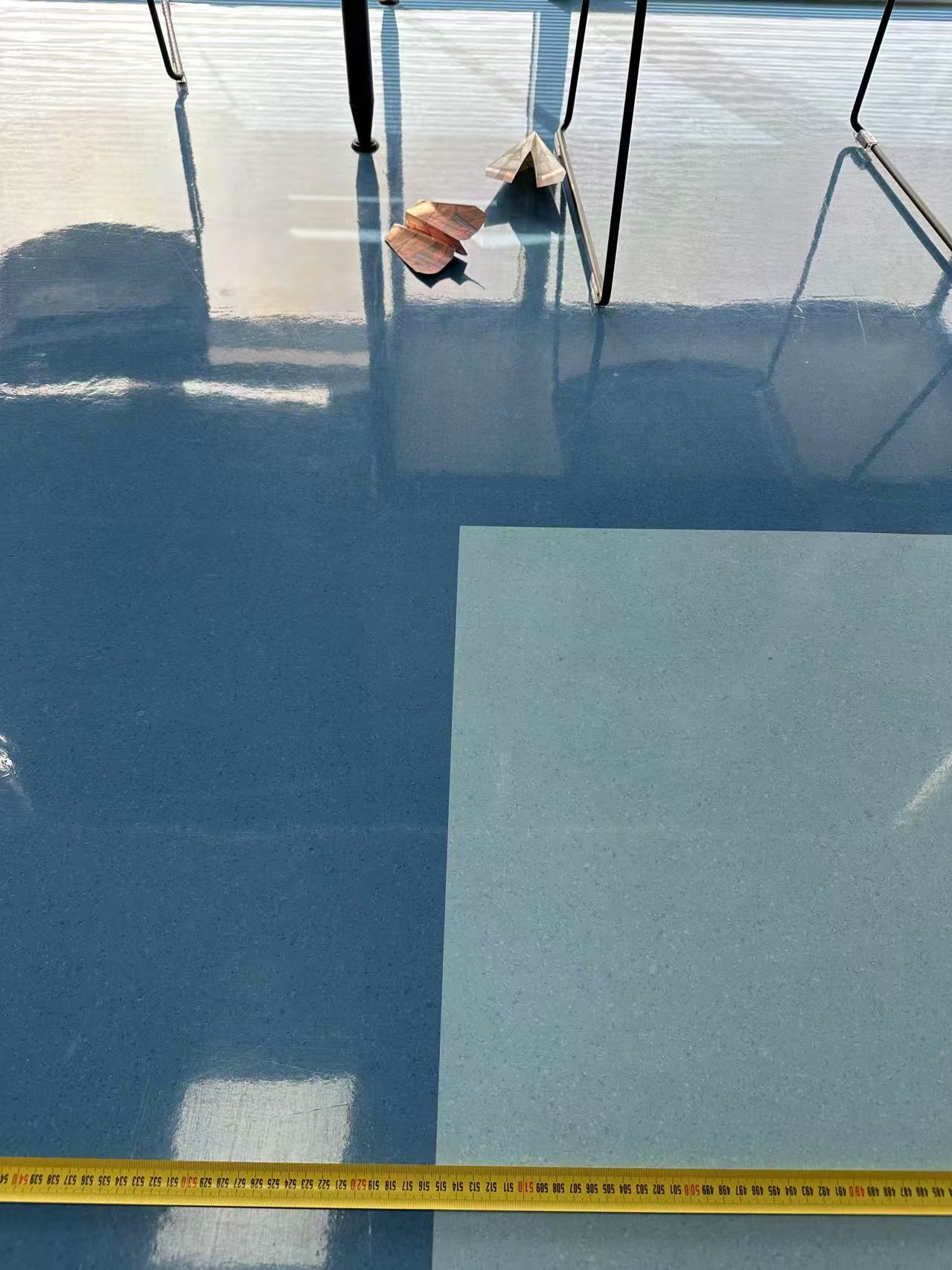
Fig 6: Side-by-side comparison of all three plane designs before test flight 2.
I have done a test flight for each of them.
#4 Plane did the worst as predicted, the results of the rest of them are pretty close. They all fly over 5 meters. The problem is that both planes’ tracks got curved during the flight. This curvature suggests minor asymmetries in the fold geometry, which create unequal drag on the left and right sides of the aircraft and induce a turning moment (Anderson, 2016).
Result
| Plane No. | 3 | 4 | 6 |
|---|---|---|---|
| Distance (cm) | 583 | 115 | 514 |
| Drift Direction | Yaw right | Massive rotation | Pitch up |
Aerodynamics
#3 Yaw
I suspect yaw is primarily caused by fold asymmetry, because the rest of the parts of the plane looks perfect aligning with aerodynamic considerations. Even small differences create a drag imbalance that matters during flight. Specifically, if the right wing has a slightly larger surface area or a slightly different angle of incidence compared to the left wing, it will generate more drag on that side, causing the aircraft to rotate about its vertical axis (Anderson, 2016).
#6 Pitch
The pitch-up behavior suggests the plane is tail-heavy or has an effective up-elevator due to wing curvature. This causes the head to rise and the plane to climb abruptly before stalling. This is an example of longitudinal instability: when the CG is aft of the CL, any small upward perturbation is amplified rather than corrected, leading to a pitch-up, stall, and eventual nosedive sequence (Tennekes, 2009).
#4 Overall Failure
Plane #4 exhibited severe instability immediately upon launch. The combination of high parasitic drag from its blunt nose and likely CG misalignment (due to the misaligned fold lines noted in the Diagnose section below) made it aerodynamically unviable. It was excluded from further comparative analysis as it did not achieve stable flight.
Diagnose
I checked #4 and found that the original printing of the folding guide lines are already misaligned. This means that even with perfect folding technique, Plane #4 would have had built-in asymmetry, which the wings would be unequal in area and angle, the nose geometry would be off-center, and the CG would be displaced laterally.
Conclusion
Across all 3 test flights, #4 performed worst as predicted: after I launched it, it was like hitting an obstacle and suddenly stalled. #3 and #6 both exceeded ~5 meters, but neither was perfectly stable. Both showed curved trajectories, suggesting they have either minor folding asymmetries or trim imbalances. Another reason might be that #6’s wings are larger and catch more wind, which generates an upward force from it. #3 does not have this problem because the wings are thin and close to the center of mass.
References
Anderson, J. D. (2016). Introduction to Flight (8th ed.). McGraw-Hill Education.
Blackburn, K. (2006). The World Record Paper Airplane Book. Workman Publishing.
Kuipers, J. B. (2002). Quaternions and Rotation Sequences. Princeton University Press.
NASA. (2021). “Four Forces of Flight.” NASA Glenn Research Center. https://www.grc.nasa.gov/www/k-12/airplane/forces.html
Tennekes, H. (2009). The Simple Science of Flight: From Insects to Jumbo Jets (Revised ed.). MIT Press.