This is an assignment on timeline in aerospace for the AL Aerospace Engineering course at Concordia International School conducted by Dr. Peter Tong (aka D.T). This article documents the design, construction, and iterative testing of an unpowered balsa wood glider as a hands-on exploration of fundamental aerospace principles.
Objectives
To build a stable airplane that will fly the farthest.
Guiding Questions
- How does the position of the Center of Gravity (CG) affect glide stability and distance?
- How does the wing aspect ratio (length/width) affect the lift and drag?
- What effect does the vertical stabilizer have on maintaining stability?
- How do adjustments to the horizontal stabilizer angle affect the pitch stability?
- What modifications can be made to the airplane to reduce drag without significantly compromising lift?
Materials
- Balsa Sheet (1.5×75mm × 915mm) (1 pc)
- Balsa Strut (5×5×50mm) (1 pc)
- Hot Glue or Standard Wood Glue
- Cutting knife
- Ruler
- Cutting board
- Rubber bands (2 pcs)
Balsa wood is selected as the primary construction material due to its exceptionally high strength-to-weight ratio. Despite having a density as low as 100–200 kg/m³, balsa maintains sufficient structural rigidity to withstand aerodynamic loads during flight (Soden & McLeish, 1976). This allows the aircraft to achieve minimal wing loading while preserving structural integrity. Additionally, balsa is much easier to cut than other materials, which enables precise configuration design during construction.
Material Property: Grain Orientation
When working with a sheet of balsa wood, cuts made parallel to the grain tend to proceed smoothly with less resistance. In contrast, cuts made perpendicular to the grain generally require substantially greater effort. These findings indicate that the compressive strength of balsa wood is significantly greater along the longitudinal grain axis. During flight, the main wing structure is subjected to distributed aerodynamic lift forces acting along its span, inducing bending moments about the wing root. When the wood grain is oriented parallel to the spanwise direction, that is, perpendicular to the fuselage centerline, the structure demonstrates enhanced resistance to bending deformation. Conversely, when the grain orientation is perpendicular to the primary loading direction, the interlaminar shear strength is reduced, rendering the structure more susceptible to flexural deformation and potential failure. This anisotropic behavior is a well-documented characteristic of balsa wood and is critical to consider during wing construction (Da Silva & Kyriakides, 2007).
Design and Construction
Building Process
First, I cut out 3 balsa pieces and prepared a wooden stick as shown in Figures 1 and 2.
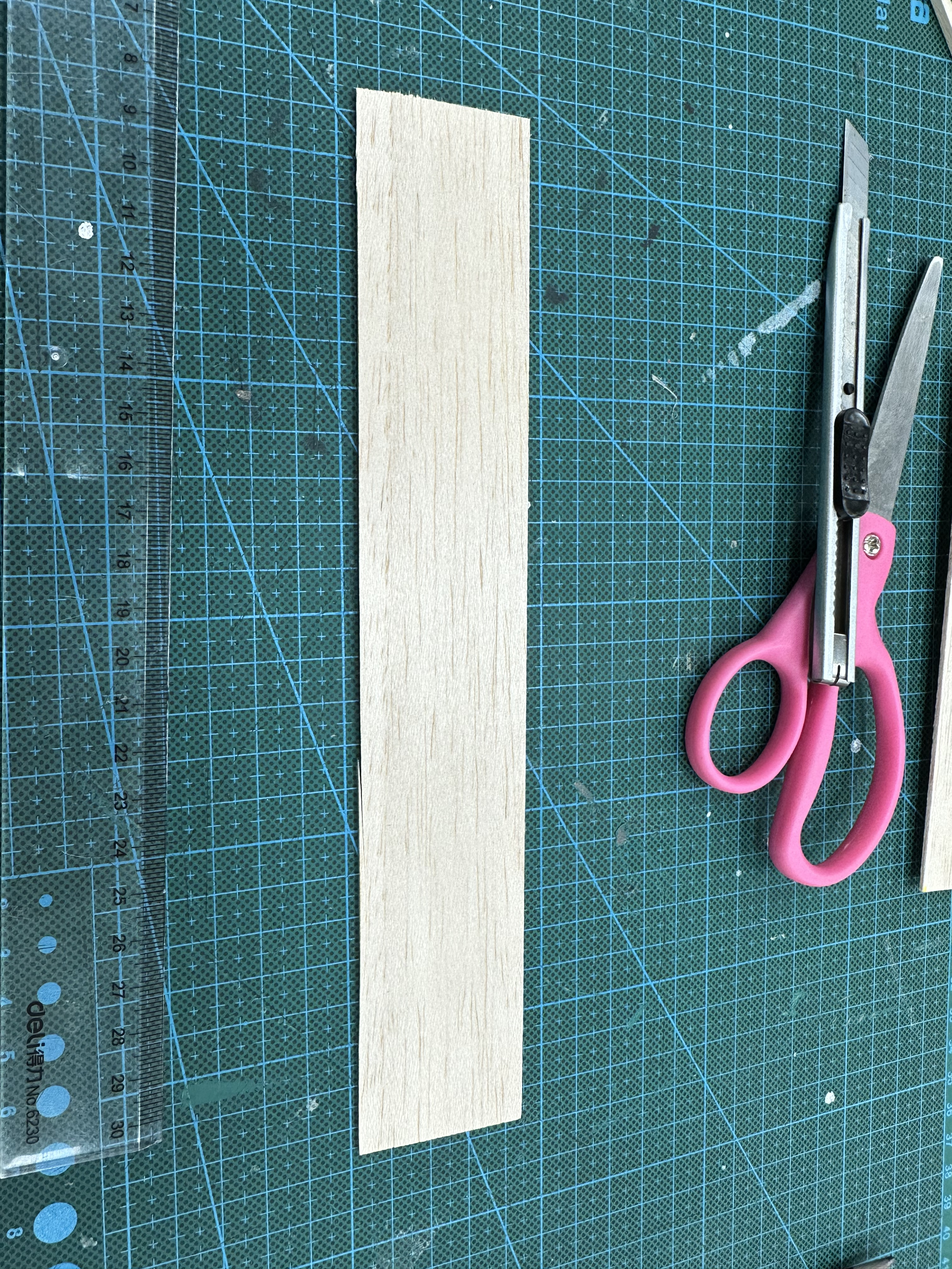
Figure 1: Raw Materials (Section) 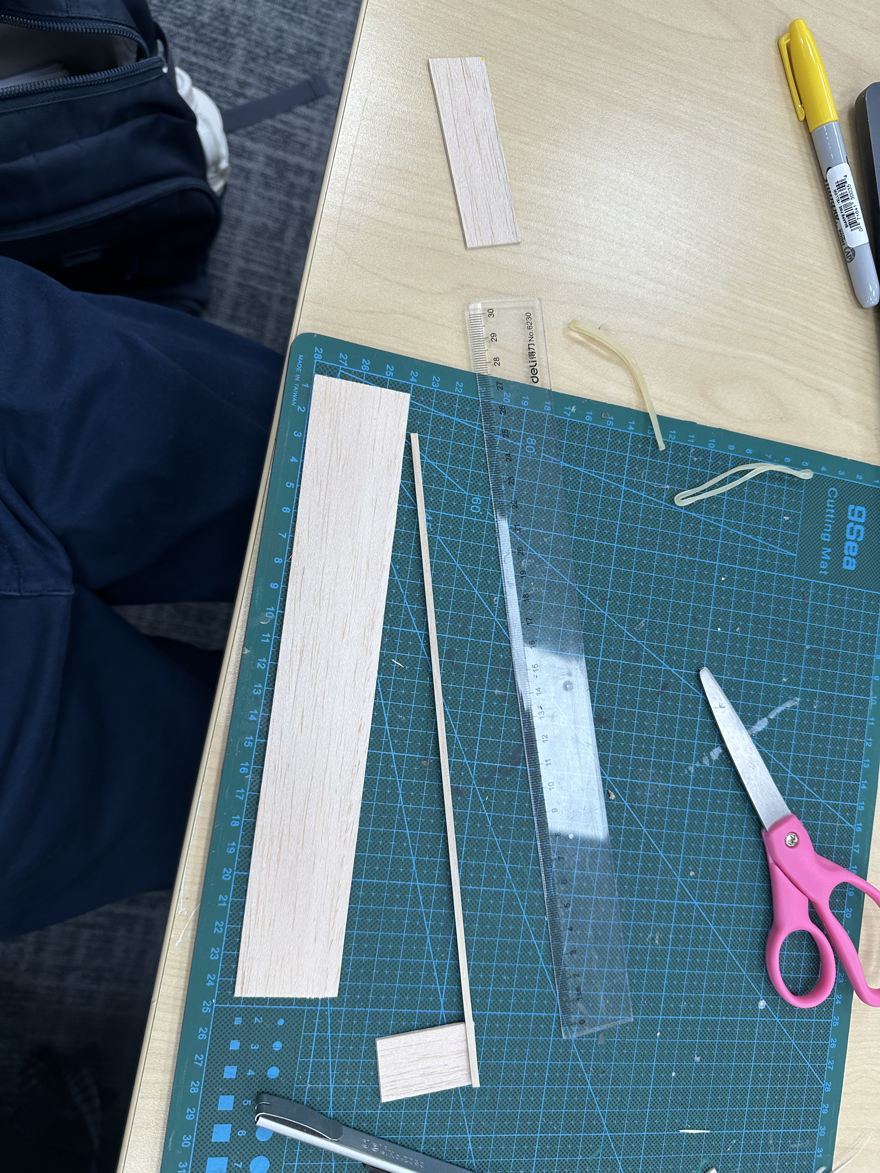
Figure 2: Vertical Stabilizer Assembled
2 rubber bands were used to fasten the main wing and the horizontal stabilizer on the fuselage, as shown in Figure 3. Figure 4 shows the assembly just before adding nose ballast (Blu-Tack).
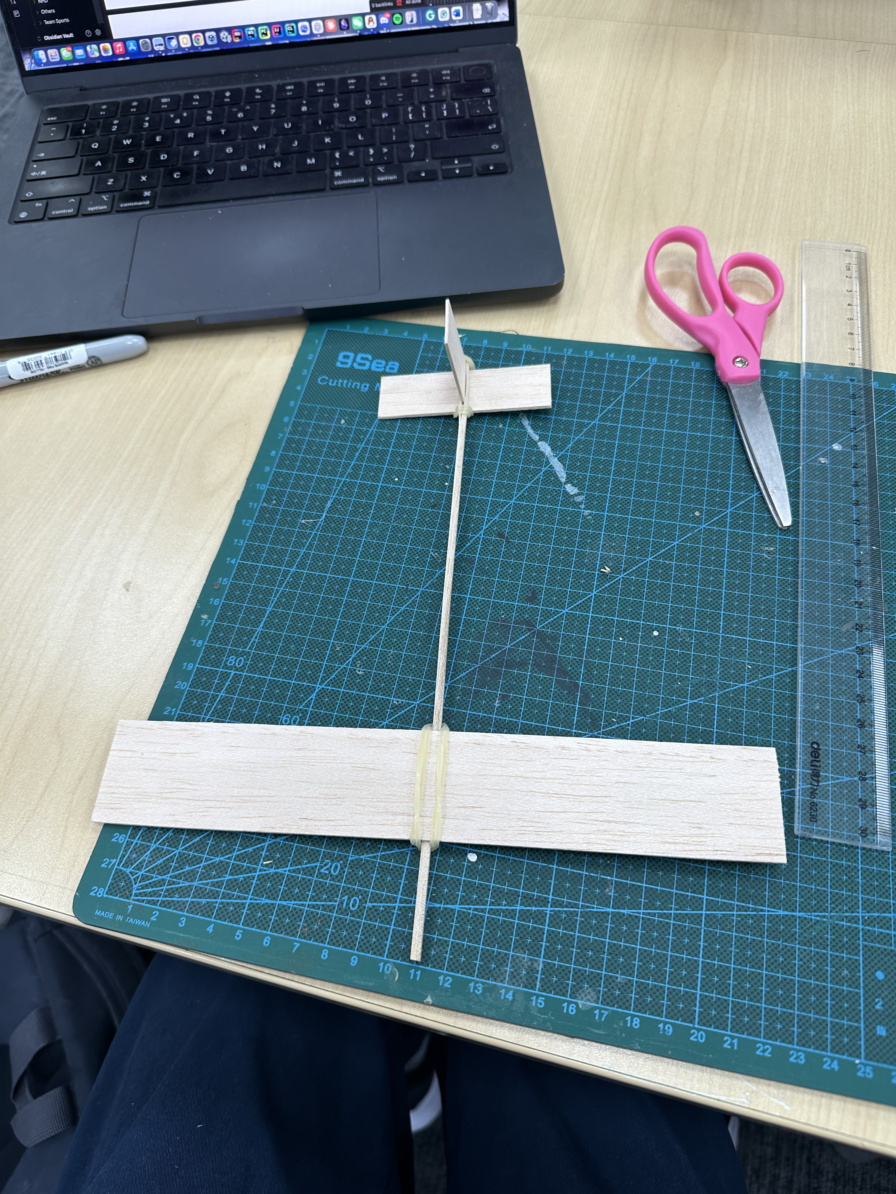
Figure 3: Wing and Stabilizer Assembled
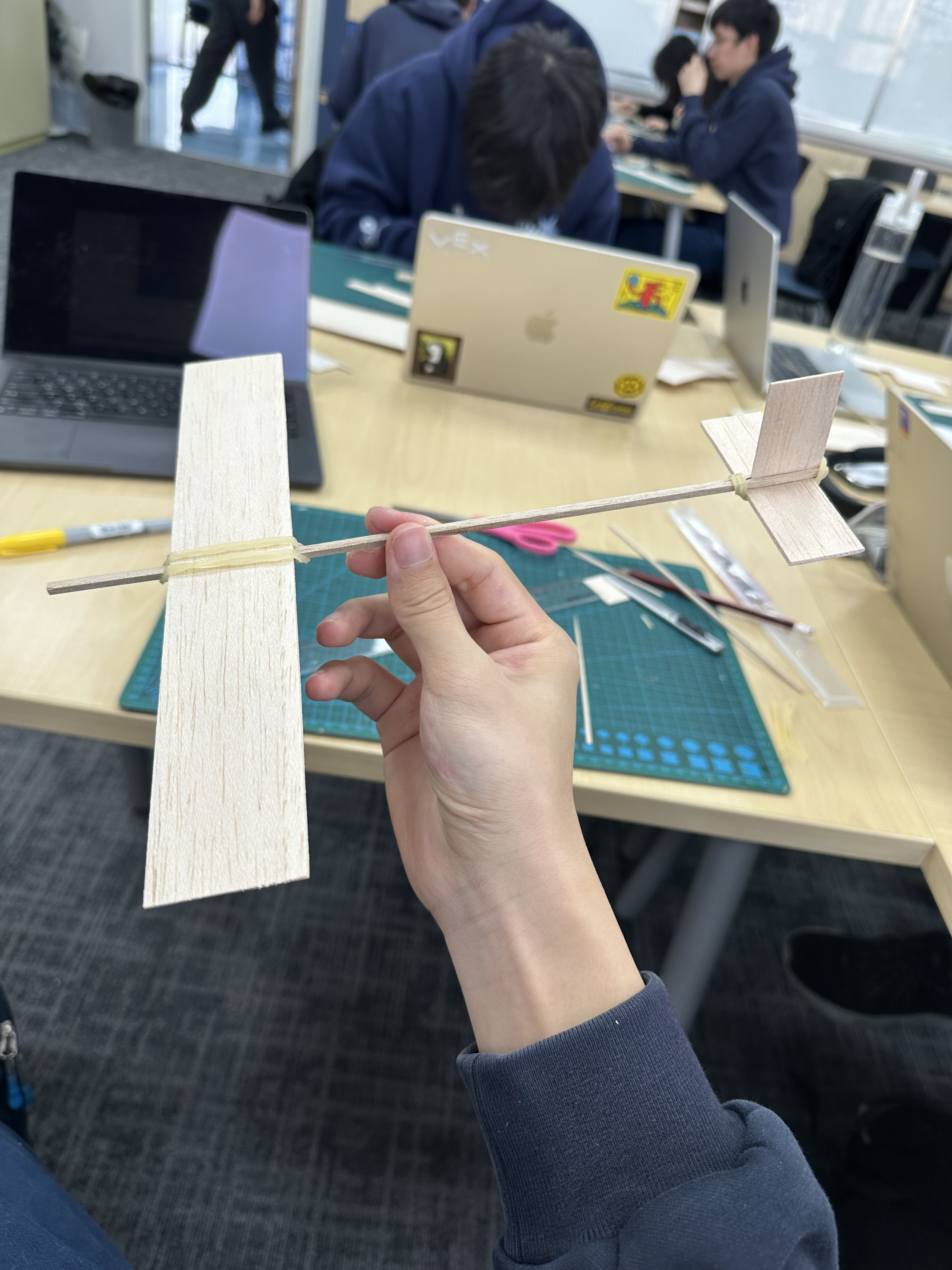
Figure 4: Final Step Before Adding Blu-Tack
Initial Configuration
The completed glider is shown in Figures 5 and 6. The initial dimensions were as follows:
- Wing:
- Horizontal Stabilizer:
- Vertical Stabilizer:
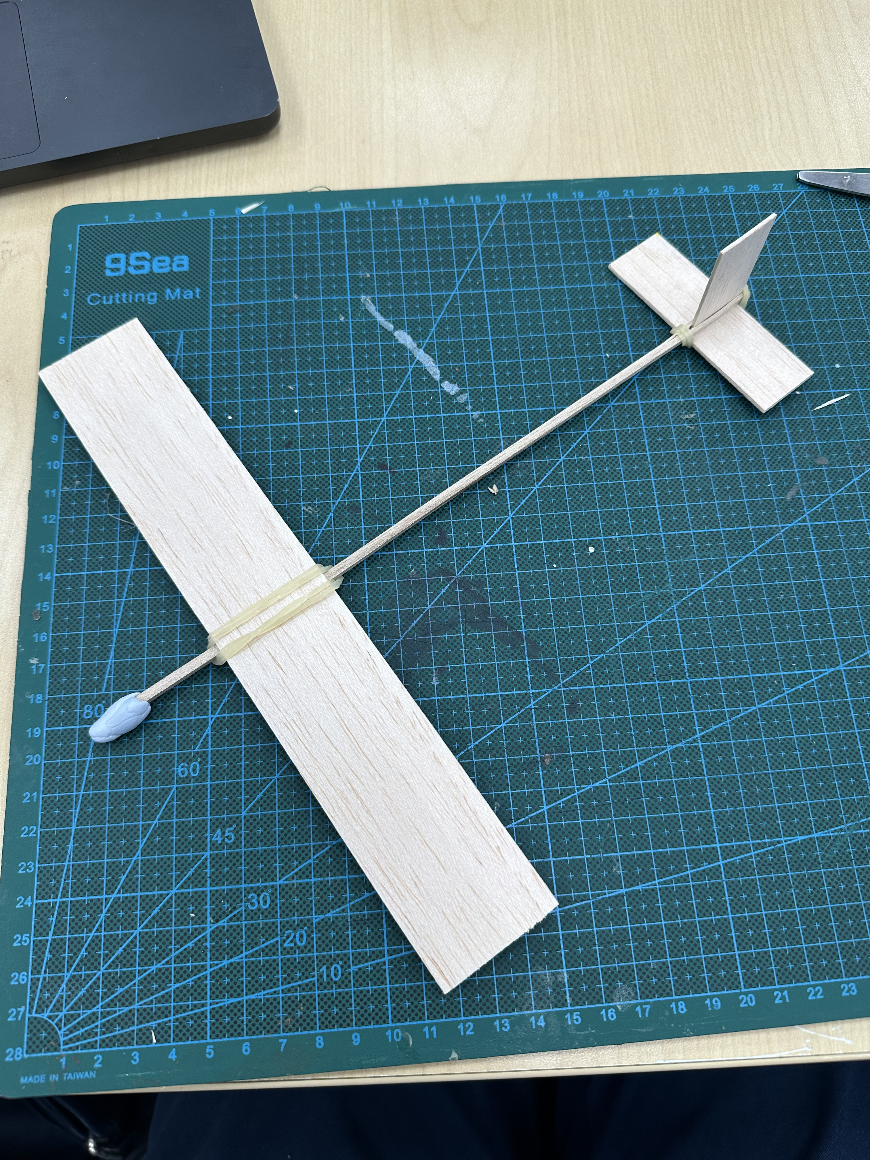
Figure 5: Airplane Top View 1
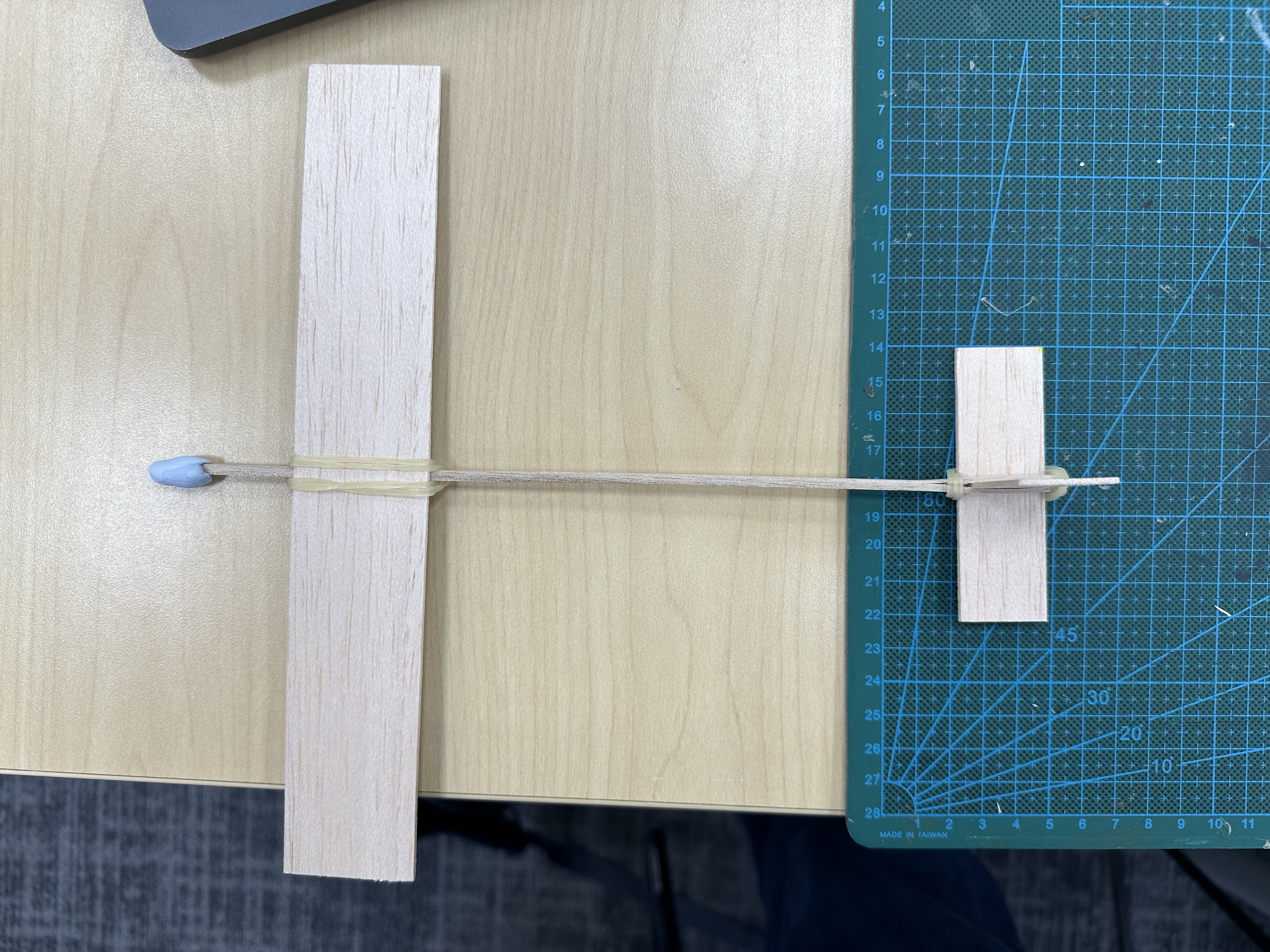
Figure 6: Airplane Top View 2
Balancing
An additional balsa wood stick was utilized to determine the center of mass of the aircraft, ensuring equilibrium along both the fuselage axis and the spanwise direction of the main wing, as shown in Figures 7 and 8. The center of mass was found to be positioned along the longitudinal centerline of the aircraft, slightly aft of the main wing.
.png)
Figure 7: Center of Mass Measurement 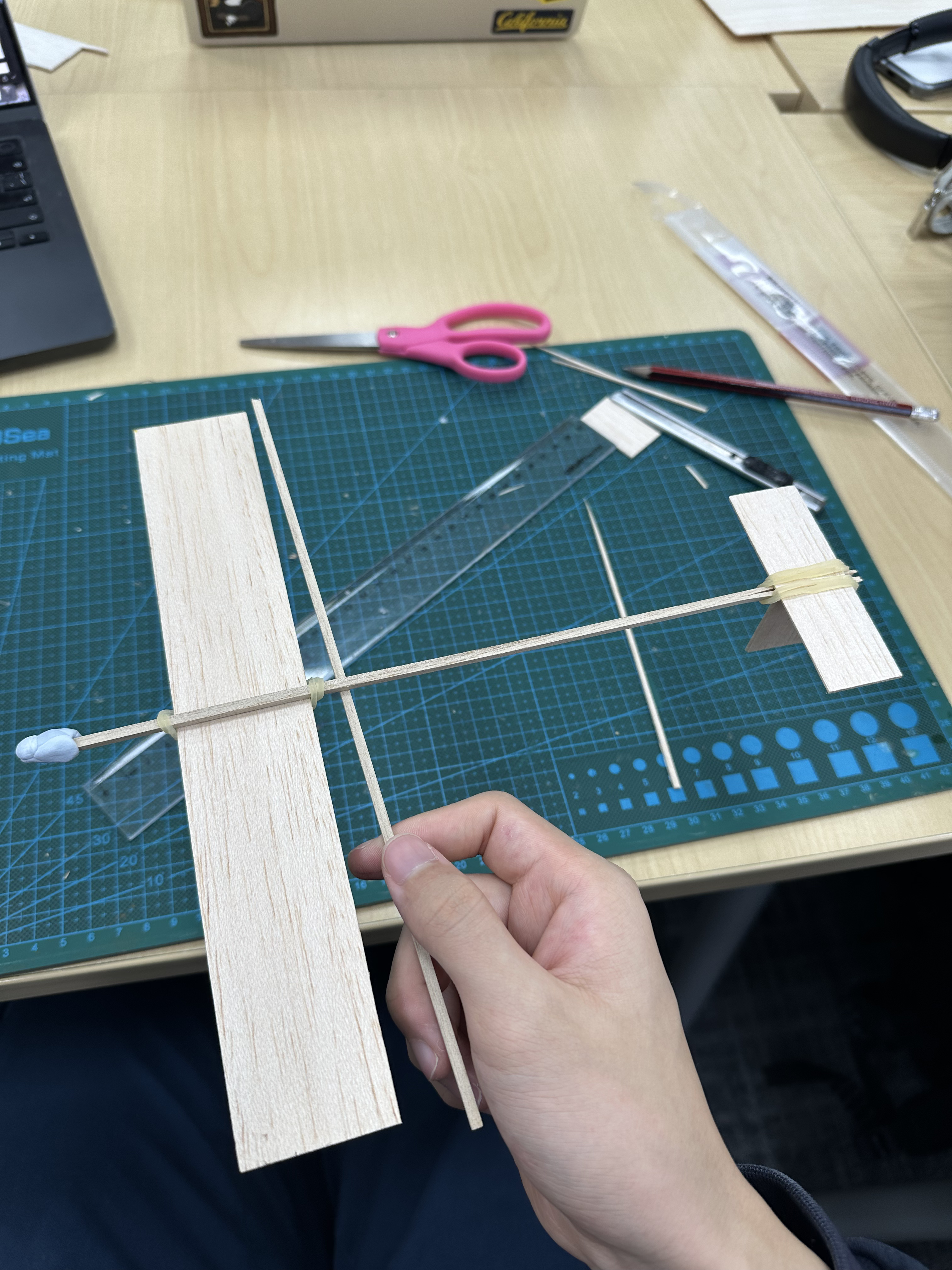
Figure 8: Center of Mass Along Fuselage Measurement
Based on this initial CG position, the aircraft was expected to maintain a brief period of level flight before experiencing a rapid loss of lift, resulting in an immediate stall to the ground.
Flight Testing and Iteration
Trial #1
Upon release, the aircraft exhibited a pronounced pitching moment and reached an angle of about 45 degrees above the ground level, leading to a stall immediately following the launch phase.
Analysis
Compared to physics, where objects are often idealized as point masses, engineering requires us to account for the effects of torque due to the actual geometry and mass distribution of components to make sure we are aware of the kinematics. Figure 9 illustrates the free body diagram used to analyze the forces and moments acting on the glider.
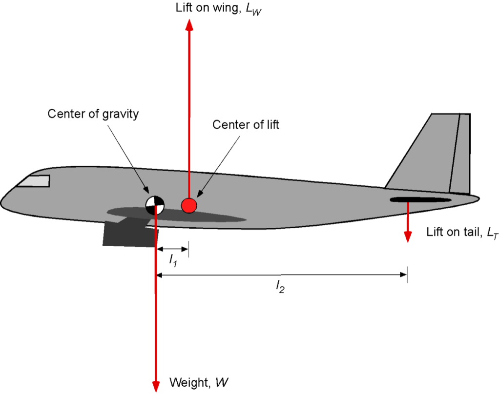
Figure 9: Free Body Diagram of Airplane
To understand why Trial #1 failed, it is necessary to examine two key concepts: center of gravity and center of lift.
Center of Gravity
The center of mass depends solely on how mass is distributed within an object. It is an intrinsic property of the body itself, independent of external forces or reference frames. For gravitational analysis, the entire weight of an object can be treated as acting through this single point.
Center of Lift
The center of lift is an aerodynamic property that depends on multiple dynamic factors: wing geometry, airflow conditions, and flight variables such as angle of attack, flap deployment, and wing configuration (Anderson, 2016). Because these factors are all variable during flight, the center of lift is inherently dynamic.
Interaction Between CG and Center of Lift
When the center of lift is behind the center of mass, the aircraft tends to pitch down, since the lift force acts behind the pivot point, pulling the tail up. When the center of lift is ahead of the center of mass, the aircraft pitches up, as lift now pushes the front end upward.
In a conventionally stable aircraft, the CG is positioned forward, with the main wing’s center of lift located slightly aft of the CG. The horizontal stabilizer at the tail generates a downward balancing force to maintain trimmed flight (Raymer, 2018). This arrangement ensures longitudinal stability, so that if the aircraft experiences an up-pitching perturbation, the resulting aerodynamic moment produces a restoring pitch-down tendency, naturally correcting the deviation rather than allowing divergence.
In Trial #1, the CG was positioned too far aft relative to the center of lift, which caused the nose-up pitching moment observed at launch.
Trial #2
In this configuration, the main wing was adjusted aft to reposition the center of lift further behind the CG, and additional weight (Blu-Tack) was applied to the nose to move the CG forward, as shown in Figure 10, enhancing longitudinal stability.
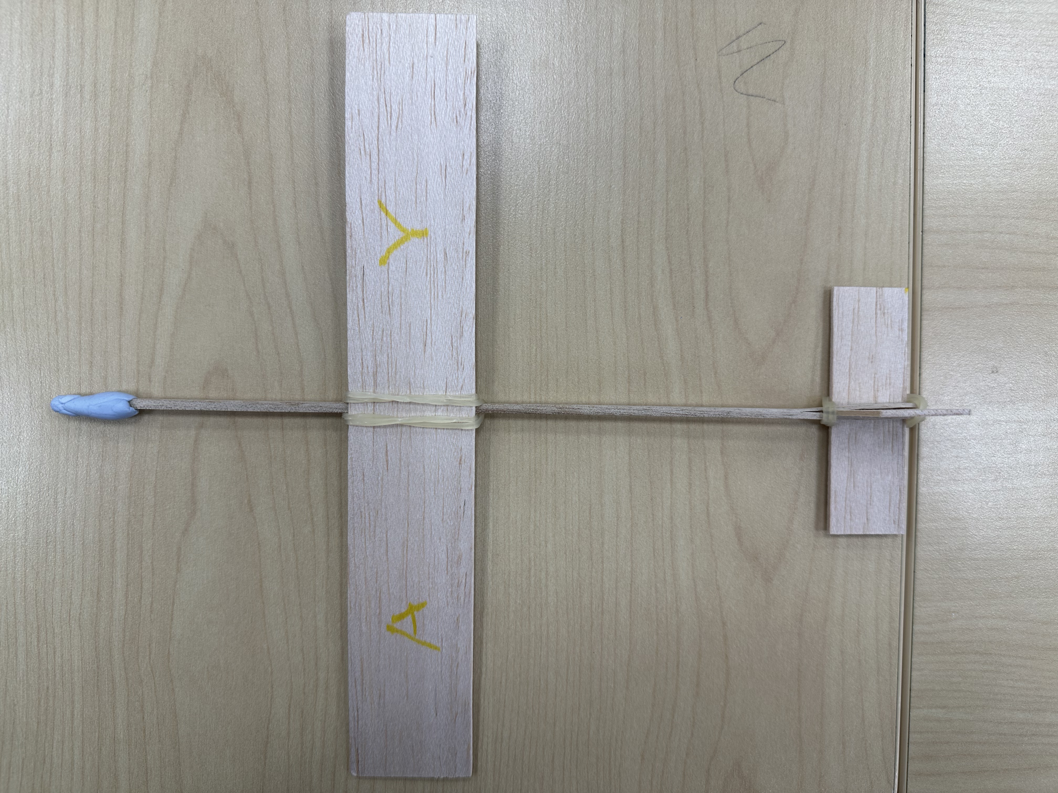
Figure 10: Trial #2 Configuration
Following this modification, flight performance improved significantly, and the aircraft achieved a stable glide path with negligible pitching. However, the trim was not yet optimal, so further tuning of the structure was conducted to achieve a more precise longitudinal balance.
Trial #3
As shown in Figure 11, I moved the center of mass to a position around 35% back from the leading edge of the main wing. According to general aircraft design guidelines, the CG should be located between 25% and 40% of the mean aerodynamic chord for longitudinal stability (Raymer, 2018). This is to make sure that the center of mass and the center of lift are distributed precisely.
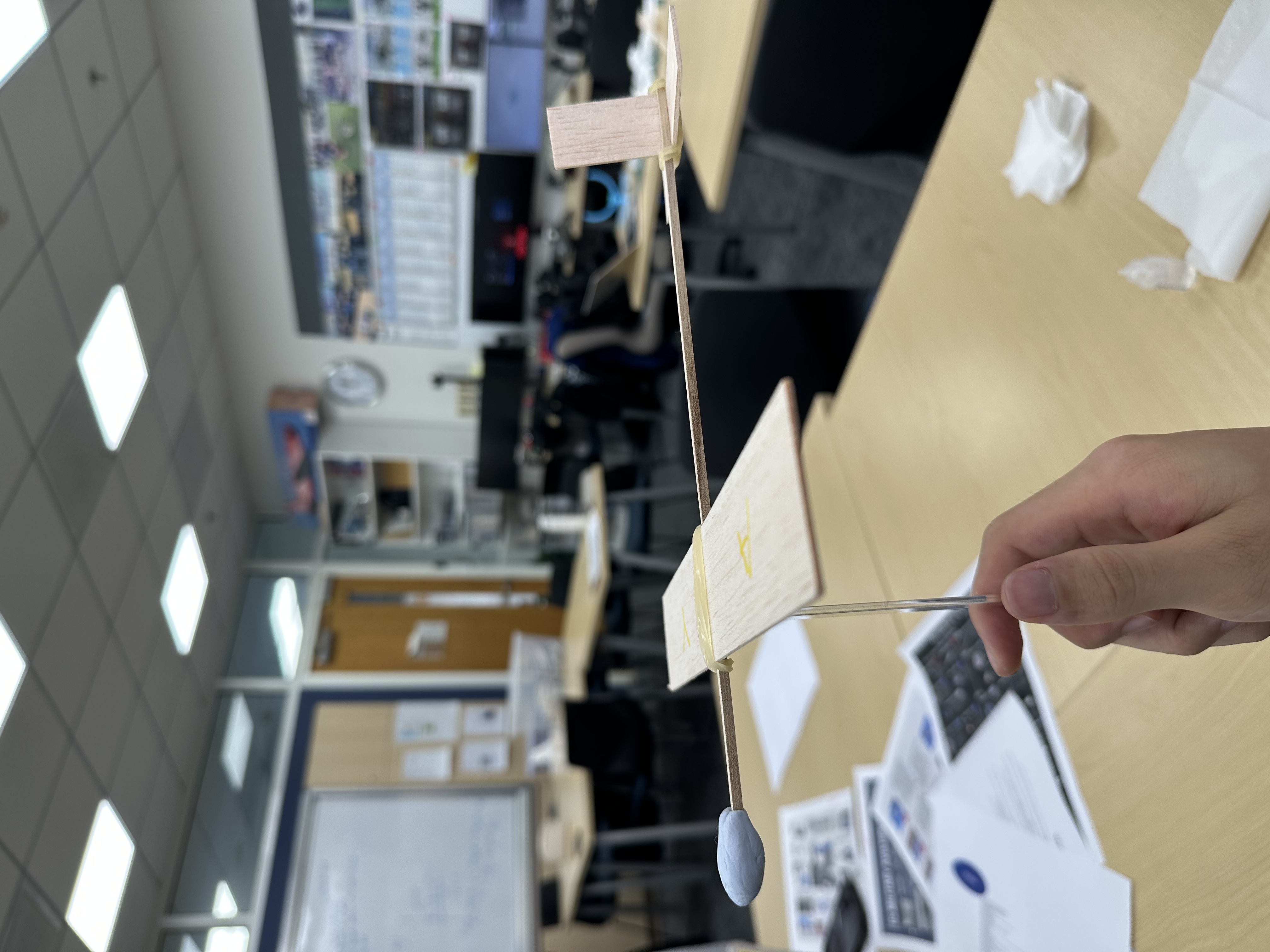
Figure 11: Trial #3 Configuration — CG Locating
This trial produced the most stable glide of the three configurations, confirming that precise CG placement is the single most impactful variable in glider trim.
Lateral Stability: Dihedral
Beyond longitudinal stability, lateral stability is equally important for a glider that must fly straight without rolling off course. This section examines the dihedral angle as a key design feature for lateral stability, which will be applied more extensively in the advanced design explored in Part 3.
Figures 12 and 13 illustrate the concept of wing dihedral.
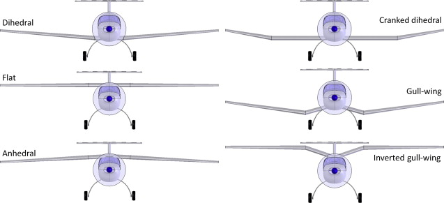
Figure 12: Schematic Diagram of Wing Configurations 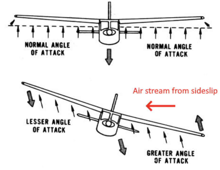
Figure 13: Schematic Diagram of Dihedral
When the aircraft sideslips toward the dropped wing, dihedral causes the lower wing to meet the airflow at a higher angle of attack as well as produce more lift, and the upper wing at a lower angle of attack as well as produce less lift. This lift asymmetry rolls the aircraft back to level.
For example, if the airplane rolls to the right, the right wing becomes lower and the left wing becomes higher. Because of changes in the airflow direction and the wing geometry, the lower wing usually gains a greater effective angle of attack and therefore more lift. As a result, the airplane is pushed back toward level flight. The primary function of dihedral is to increase an aircraft’s lateral static stability in sideslip (Raymer, 2018).
The most critical application of dihedral is during a sideslip, when the airplane is pushed off course by the wind and enters a sideslip, the relative airflow approaches from the side. The dihedral causes the left and right wings to respond differently to this sideways airflow, creating a rolling moment that tends to roll the airplane back to wings-level flight.
Advanced Design Preview
Building on the lessons from Trials 1 to 3, an advanced balsa glider was designed incorporating tapered wing panels, polyhedral dihedral, and optimized incidence angles. The design schematic is shown in Figure 14. The advanced design has a 36 cm wingspan with a total wing area of approximately 187 cm², a tapered horizontal stabilizer of about 40–42 cm², and a vertical stabilizer of about 13–15 cm², all mounted on a 26.7 cm fuselage stick. The CG target was set at 40% of the 6.0 cm center chord. Detailed dimensions, material allocation, and construction notes for this design will be documented fully in Part 3.
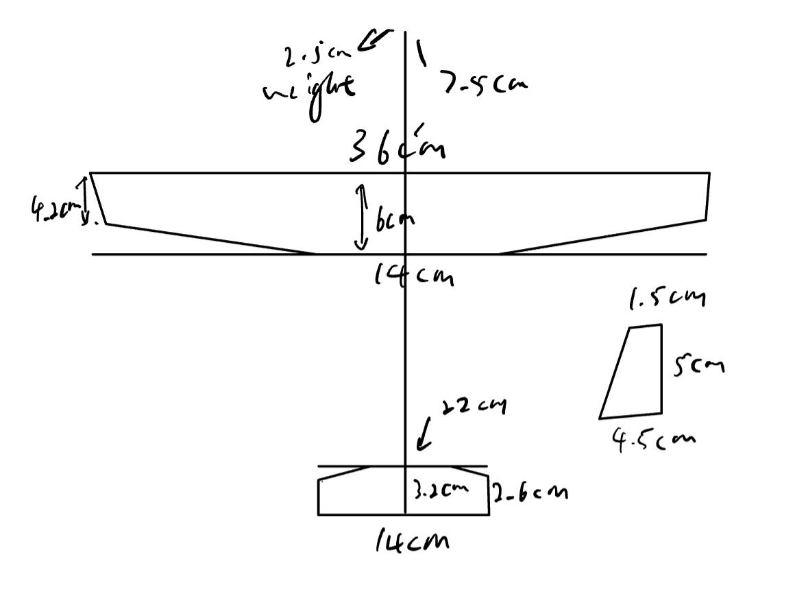
Figure 14: Enhanced Balsa Airplane Design
Construction
The advanced glider was built according to the design in Figure 14. Figures 15–18 document the completed construction from multiple angles.
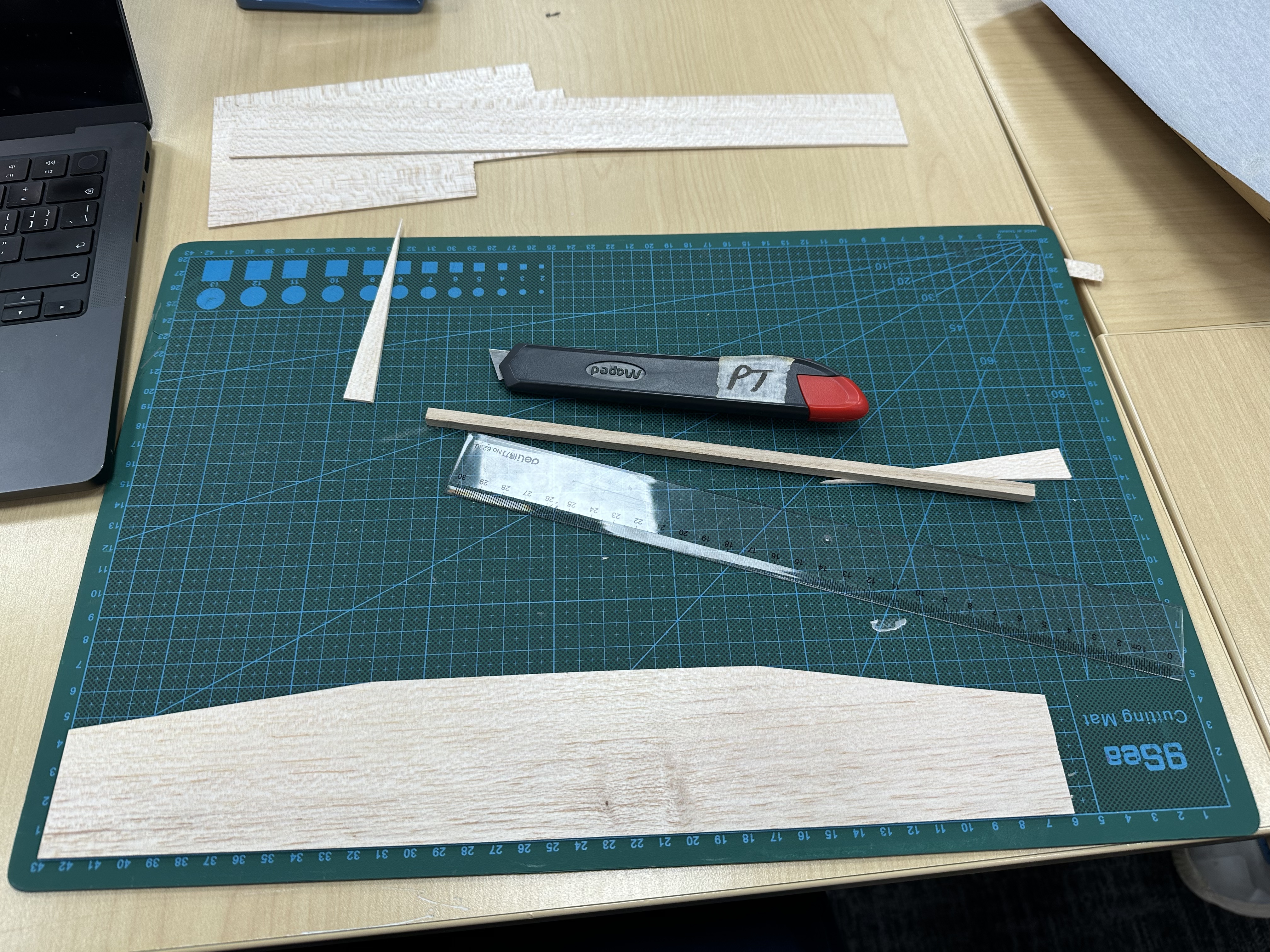
Figure 15: The Wing 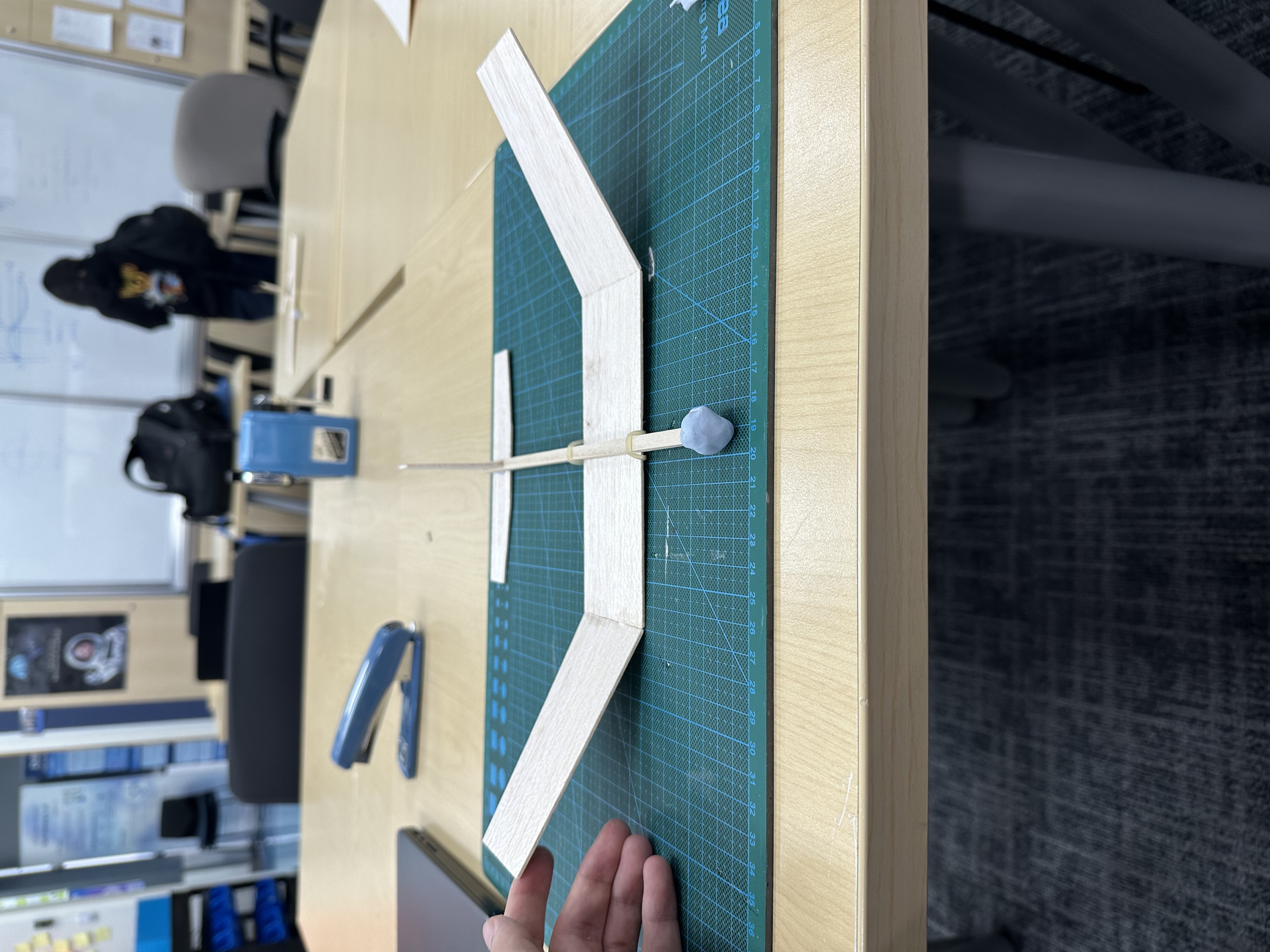
Figure 16: Front View 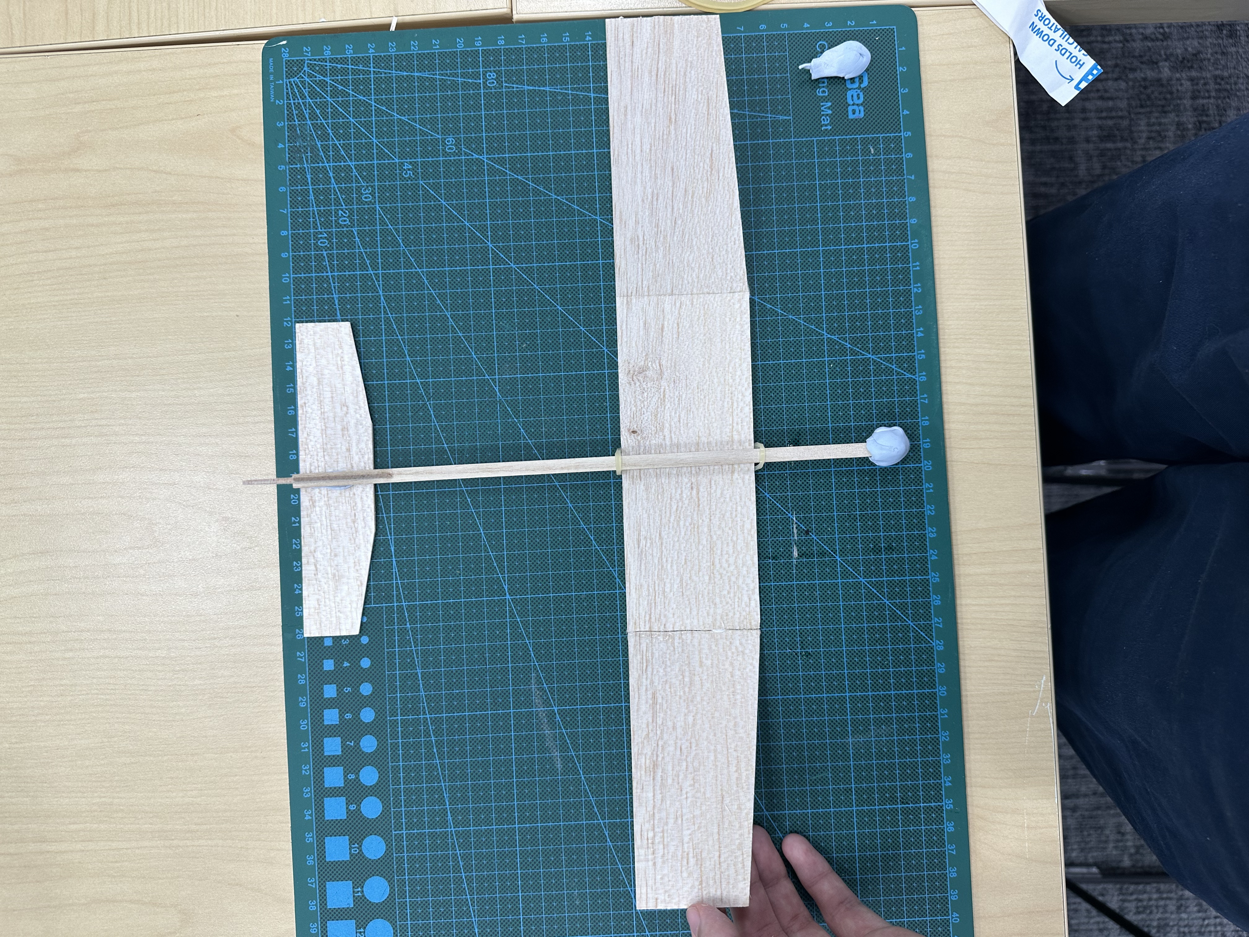
Figure 17: Top View 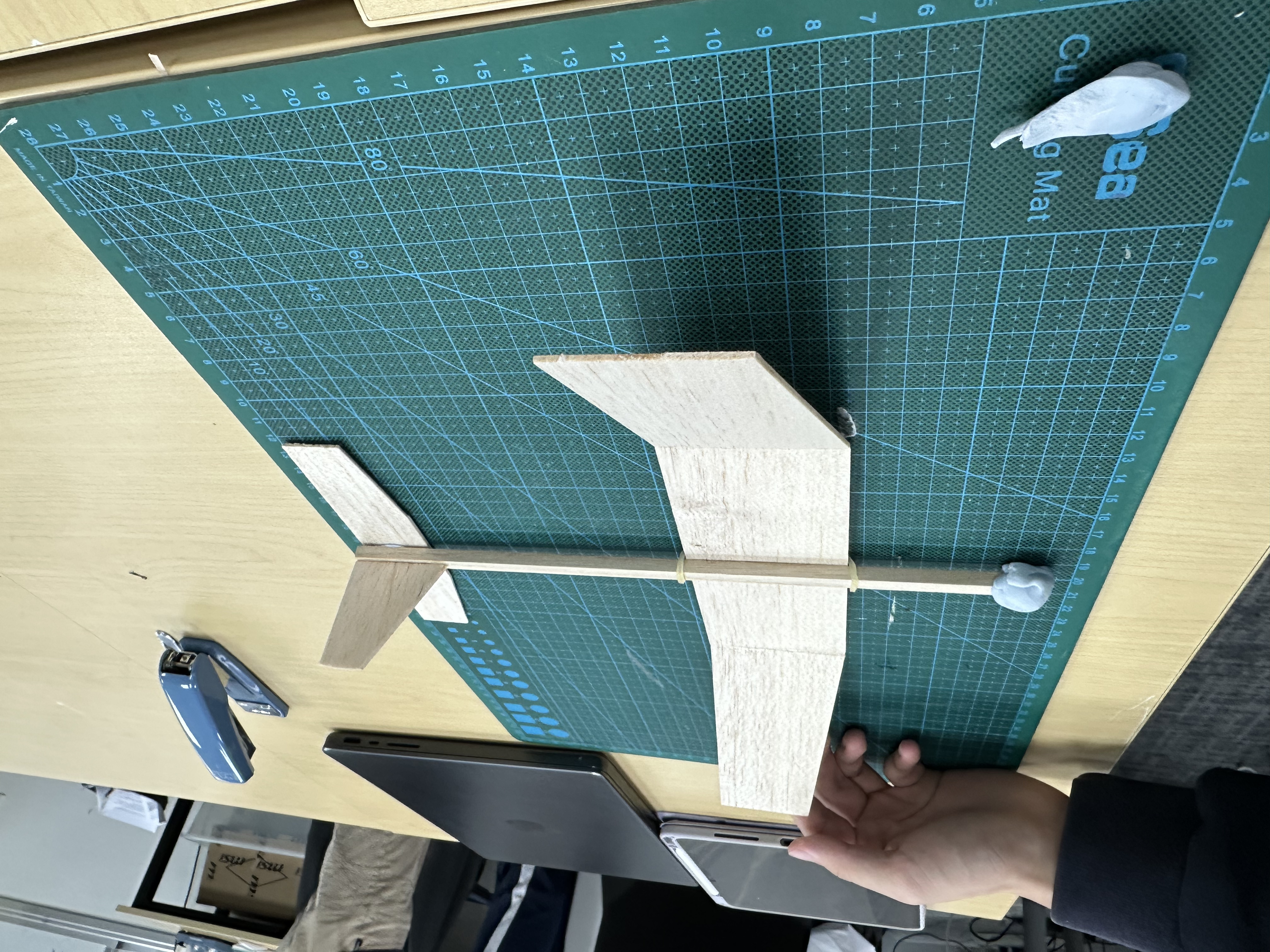
Figure 18: Side View
Final Trial
The advanced glider was test-flown and the trajectory was recorded (Video 1).
Video 1: Recording of Trajectory
Observed Flight Behavior
The glider descended steeply from the launch point and drifted into a left turn laterally.
Probable Causes
- CG too far forward: excessive down-pitching moment.
- Asymmetric wing geometry or warp: if one wing has slightly more incidence or drag than the other, it induces a rolling moment that leads to a turning trajectory.
Proposed Improvements
- Shift CG slightly aft: remove a small amount of weight (Blu-Tack) at the leading edge so the glide angle flattens out.
- Check wing symmetry: check and make sure both wings have identical dihedral, incidence, and no warping.
Comparison
Through comparison with other aircraft, weight was also identified as a non-negligible factor. Referencing Andy’s aircraft, which weighed approximately 4 grams, my aircraft weighed 12 grams, three times heavier. A higher mass increases the wing loading, requiring greater airspeed to sustain level flight. At the same launch velocity, the heavier aircraft loses altitude more rapidly, resulting in a steeper glide path and shorter flight distance. This relationship is consistent with the fundamental wing loading equation used in aircraft performance analysis (Anderson, 2016).
References
Anderson, J. D. (2016). Introduction to Flight (8th ed.). McGraw-Hill Education.
Da Silva, A., & Kyriakides, S. (2007). Compressive response and failure of balsa wood. International Journal of Solids and Structures, 44(25–26), 8685–8717.
Raymer, D. P. (2018). Aircraft Design: A Conceptual Approach (6th ed.). AIAA Education Series.
Soden, P. D., & McLeish, R. D. (1976). Variables affecting the strength of balsa wood. Journal of Strain Analysis for Engineering Design, 11(4), 225–234.